Positive flow excavator power and torque distribution control method

A technology of torque distribution and control method, which is applied in earth mover/excavator, construction, etc., and can solve the problems of unstable load, large variation range, unstable engine load and speed, etc.

Active Publication Date: 2020-02-04
SHANDONG LINGONG CONSTR MACHINERY
View PDF6 Cites 0 Cited by
  • Summary
  • Abstract
  • Description
  • Claims
  • Application Information

AI Technical Summary

Problems solved by technology

During the operation of the excavator, the engine speed is generally set at a fixed speed according to the working conditions. However, due to the unstable load and large variation range, the engine load and speed are unstable. When the load exceeds the external characteristic curve of the engine It will cause the engine speed to drop greatly, the car to stall and the fuel consumption to be high.
The change of the load causes the pressure of the two variable displacement plunger pumps to change, and the increase of the pressure will cause the main pump to absorb power and torque to increase, resulting in a decrease in the engine speed, and deterioration of the overall efficiency and controllability

Method used


Image

  • Positive flow excavator power and torque distribution control method
  • Positive flow excavator power and torque distribution control method
  • Positive flow excavator power and torque distribution control method

Examples


Embodiment

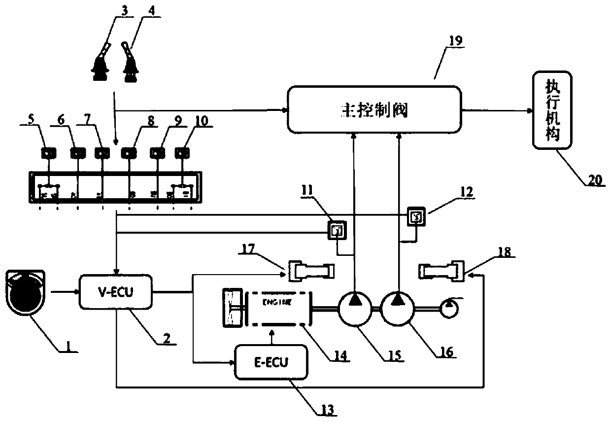
[0050] Such as Figure 1 to Figure 3 As shown, the power and torque distribution control method of a positive flow excavator, the excavator includes a gear selector 1, a main controller 2, a left pilot control valve 3, a right pilot control valve 4, a rotary pilot pressure sensor 5, an arm discharge Material pilot pressure sensor 6, stick digging pilot pressure sensor 7, boom lowering pilot pressure sensor 8, boom lifting pilot pressure sensor 9, bucket digging / discharging pilot pressure sensor 10, P1 pump pressure sensor 11, P2 pump Pressure sensor 12, engine controller 13, engine 14, P1 pump 15, P2 pump 16, P1 pump swash plate angle regulator 17, P2 pump swash plate angle regulator 18, main control valve 19, actuator 20, main pump, P1 pump electromagnetic proportional valve, P2 pump electromagnetic proportional valve, boom cylinder, arm cylinder, bucket cylinder, swing motor and travel motor, the excavator provides power to P1 pump 15 and P2 pump 16 through engine 14, and P1...


PUM


Abstract

The invention relates to the technical field of engineering machines, in particular to a positive flow excavator power and torque distribution control method. The method comprises the following stepsthat firstly, the demand displacement D1r of a P1 pump and the demand displacement D2r of a P2 pump are calculated; secondly, the actual displacement D1 of the P 1 pump and the actual displacement D2of the P2 pump are calculated; and thirdly, the torque and output displacement of the P1 pump and the P2 pump are adjusted and controlled according to the actual displacement D1 of the P 1 pump and the actual displacement D2 of the P 2 pump. According to the positive flow excavator power and torque distribution control method, the torque and the output displacement of the P1 pump and the P2 pump are adjusted and controlled according to the calculated actual displacement D1 and the actual displacement D2, so that the power and torque output by an engine can be reasonably distributed to the P1 pump and the P2 pump, the rotating speed of the engine is maintained within a stable range, and fuel consumption is reduced.

Description

technical field [0001] The invention relates to the technical field of engineering machinery, in particular to a power and torque distribution control method for a positive flow excavator. Background technique [0002] As we all know, the operating conditions of excavators are mainly excavation operations and loading operations. The excavator system is mainly composed of engine, pump, control valve, oil cylinder, motor, pipeline and other accessories. The hydraulic oil pumped out by the engine-driven variable plunger pump drives the boom cylinder, stick cylinder, bucket cylinder, and swing motor. As well as other actuators such as travel motors, the boom can be raised and lowered, the stick unloading, digging, the bucket digging, unloading and turning, etc., to realize digging and loading operations. [0003] At present, the excavator hydraulic system on the market partly adopts the negative flow control system, and partly adopts the positive flow system. Compared with the ...

Claims


Application Information

Patent Timeline
Patent Type & Authority Applications(China)
IPC IPC(8): E02F9/20E02F9/22
CPCE02F9/20E02F9/22E02F9/2004E02F9/2221E02F9/2239E02F9/2246
Inventor 徐腾飞张建崔永国史广扬武香菊戚兴军于新友
Owner SHANDONG LINGONG CONSTR MACHINERY
Why Eureka
Try Eureka