Supercharge Your Innovation With Domain-Expert AI Agents!

Direct shear test device of rock cracks

A test device and rock fissure technology, applied in the field of rock and rock mass mechanics, can solve the problems of difficult rock fixation test, random rock fissure inclination, difficulty, etc.

Active Publication Date: 2020-02-04
TSINGHUA UNIV
View PDF13 Cites 4 Cited by
  • Summary
  • Abstract
  • Description
  • Claims
  • Application Information

AI Technical Summary

Problems solved by technology

[0004] For above-mentioned deficiencies in the prior art, the object of the present invention is to provide a kind of direct shear test device of rock fissure, can be used for the direct shear test device of rock fissure to the rock specimen with different fissure inclination angle, solves the problem of prior art Due to the random inclination angle of rock fissures in natural joints, it is difficult to fix the rock, which makes it difficult to carry out the test

Method used


Image

  • Direct shear test device of rock cracks
  • Direct shear test device of rock cracks
  • Direct shear test device of rock cracks

Examples


Embodiment 1

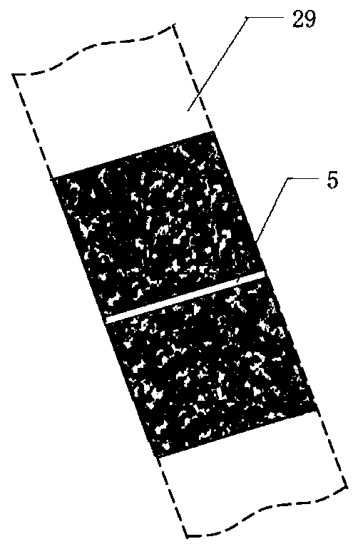
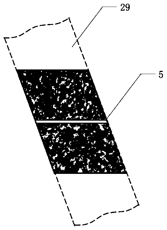
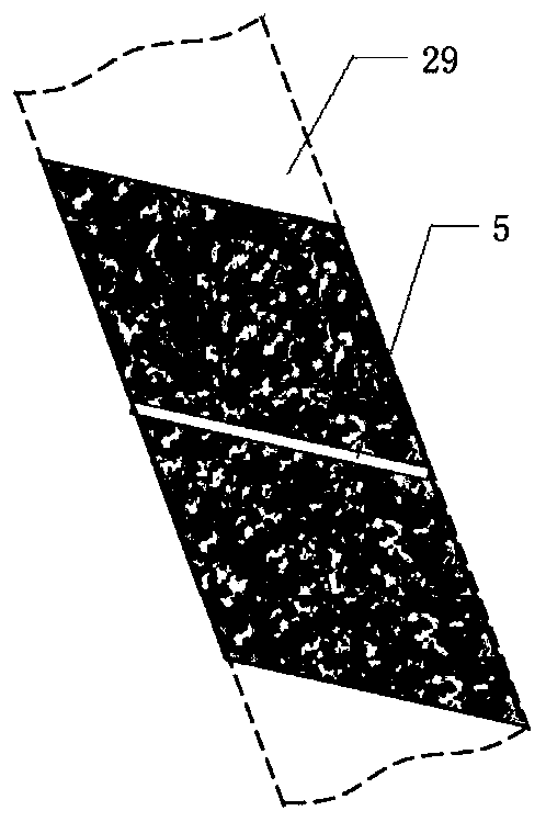
[0032] Such as Figure 2-4 As shown, the rock fracture direct shear test device provided in this embodiment includes a shear box, a positioning assembly and a heating assembly.

[0033] The shear box is formed by fastening the upper shear box and the lower shear box, and has a cavity for accommodating the test piece 4 . Both the lower shear box and the upper shear box have a square outside and a thick-walled cylindrical cavity in the middle, and the cavity is used to pour the specimen 4 with natural cement filling rock fissures; the lower shear box and the upper shear box The cutting boxes are all detachable structures, wherein the upper shearing box includes an upper box body 14 and an upper cover plate 15 that are detachably connected by fastening bolts 3, and the lower shearing box includes a lower box that is detachably connected by fastening bolts 3. The box body 1, the lower cover plate 2, the upper cover plate 15 and the lower cover plate 2 are all provided with a wate...

Embodiment 2

[0056] On the basis of Embodiment 1, an angle positioning rod 28 and a second protractor 23 are added, and the two ends of the angle positioning rod 28 are respectively provided with a third connecting hole (not shown in the figure) and a fourth connecting hole (not shown in the figure). shown), wherein the fourth connecting hole is a threaded hole, and the first orientation knob 10 can pass through the third connecting hole and the second connecting hole to make one end of the angle positioning rod 28 and the height positioning rod 9 form a detachable connection; this scheme Among them, the first protractor 11 is used to measure the angle between the angle positioning rod 28 and the horizontal direction; the second orientation knob 16 can pass through the fourth connection hole and the first connection hole to make the other end of the angle positioning rod 28 and the test piece 4. The fixture forms a detachable connection. The second protractor 23 is arranged on the angle pos...


PUM


Abstract

The invention provides a direct shear test device of rock cracks. The device is characterized in that the test device comprises a shear box and a positioning component, the shear box has a cavity accommodating a test piece, and the shear box is formed by buckling of an upper shear box and a lower shear box; and the positioning component includes a height positioning rod, a first protractor and a test piece fixture. Compared with the prior art, the direct shear test device of the rock cracks provided by the invention can fix, through arranging the positioning device which can adjust and measurean angle, rock test pieces with different crack tilt angles to meet requirements of direct shear tests; and can heat the shear box and high-temperature-resistant cement mortar and the test piece, which are poured in the shear box, through arranging heating, provides a support condition for development of direct shear tests of natural cementing filling cracks under action of high temperature, andhas great significance for exploring mechanical properties of high-temperature rock masses.

Description

technical field [0001] The invention relates to the technical field of rock and rock mechanics, in particular to a direct shear test device for rock fissures. Background technique [0002] Due to the development and changes of tectonic stress in the long geological age, crack initiation and expansion will occur in the rock mass, and then a large number of randomly distributed natural joint fissure networks will be formed, and its shear mechanical behavior and shear strength directly affect the local rock mass. stability and permeability. Most natural joints and fissures contain cemented fillings produced by geological age. These weak structural plane minerals will weaken the shear strength of joints, and then complicate the shear mechanics behavior of natural joints and fissures. In addition, for deep rock mass engineering, such as hot dry rock geothermal resource exploitation, geological deep burial disposal of high-level radioactive waste, etc., in addition to the influen...

Claims


Application Information

Patent Timeline
Patent Type & Authority Applications(China)
IPC IPC(8): G01N3/24G01N3/04G01N3/02
CPCG01N3/02G01N3/04G01N3/24G01N2203/0025G01N2203/0226G01N2203/0482
Inventor 赵志宏陈跃都赵星光
Owner TSINGHUA UNIV
Features
  • R&D
  • Intellectual Property
  • Life Sciences
  • Materials
  • Tech Scout
  • Unparalleled Data Quality
  • Higher Quality Content
  • 60% Fewer Hallucinations
Learn More