Eureka AIR delivers breakthrough ideas for toughest innovation challenges, trusted by R&D personnel around the world.

Suspension system for single-axis optical actuators

An optical actuator and single-axis technology, applied in optics, instruments, projection devices, etc., can solve the problems of volume limitation, increase of manufacturing cost, volume can no longer be reduced or thinned, etc., to achieve reliable and convenient assembly and accurate angle And the effect of durability, collocation and easy action

Active Publication Date: 2021-09-07
MIN AIK TECH
View PDF9 Cites 0 Cited by
  • Summary
  • Abstract
  • Description
  • Claims
  • Application Information

AI Technical Summary

Problems solved by technology

[0005] The existing bearing 82 and the rotating shaft 83 are used as the fulcrum, but there is a gap between the bearing 82 and the rotating shaft 83, so when it swings up and down on both sides of the fast, the position of the fulcrum itself will jump up and down due to the gap, or the rotating shaft 83 is in the bearing. There will also be an axial offset in the 82, which makes the position of the light projection change from time to time due to the gap and axial displacement, resulting in unpredictable errors, and the resolution is not stable, which is the main shortcoming of the existing
[0006] A bearing 82 is provided on the base 81 of the actuator 80, and the volume can no longer be reduced or thinned, which limits the volume of the product and does not have the prospect of subsequent product promotion, which is another shortcoming
[0007] For the bearing 82 and the rotating shaft 83 as the fulcrum, the cost of using the actuator 80 is still on the high side, which increases the manufacturing cost. At the same time, the maintenance and replacement after wear and tear all need higher costs, which is a redesign of the existing design. a shortcoming
[0008] In addition, there is still a way to replace the above-mentioned bearing as the fulcrum, using a square shrapnel as the torsion shaft, which can reduce the cost even more, but because the simple rectangular shrapnel does not have a fixed support when twisting left and right. The fulcrum makes the position of the fulcrum on the shrapnel move around every time the swinging member swings. Although the cost can be reduced, the position of the fulcrum still cannot be fixed when swinging, so the rotation axis of the shrapnel often changes, resulting in projection position The lack of control is the main disadvantage. In addition, as long as there is a slight deviation in the angle of the two ends when assembling the shrapnel, the rotation axis cannot be in the same line, and the projection position is still easy to deviate, which is another major disadvantage.

Method used


Image

  • Suspension system for single-axis optical actuators
  • Suspension system for single-axis optical actuators
  • Suspension system for single-axis optical actuators

Examples


Embodiment Construction

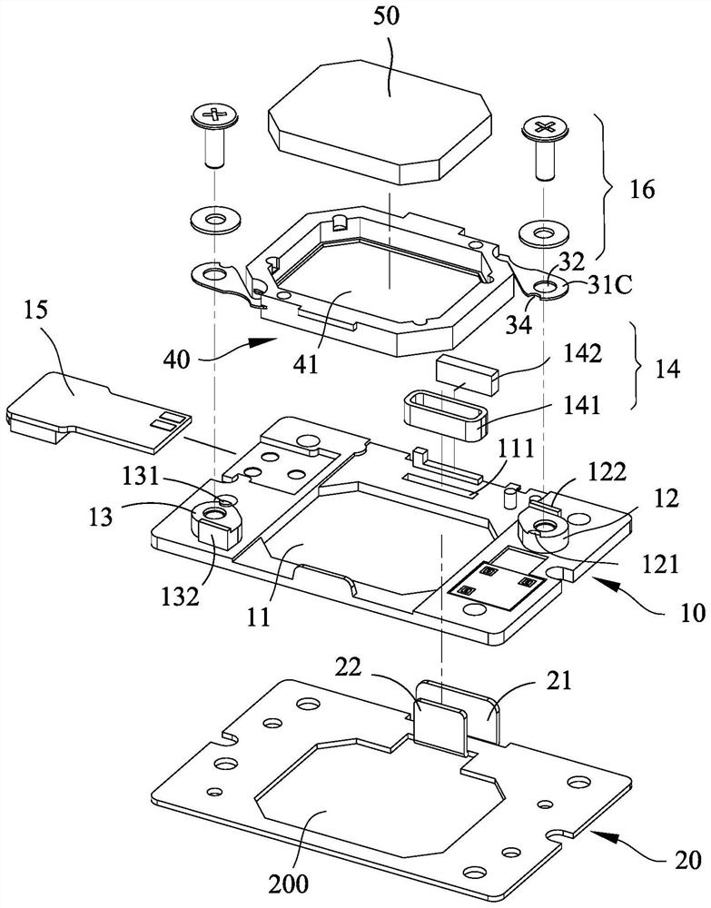
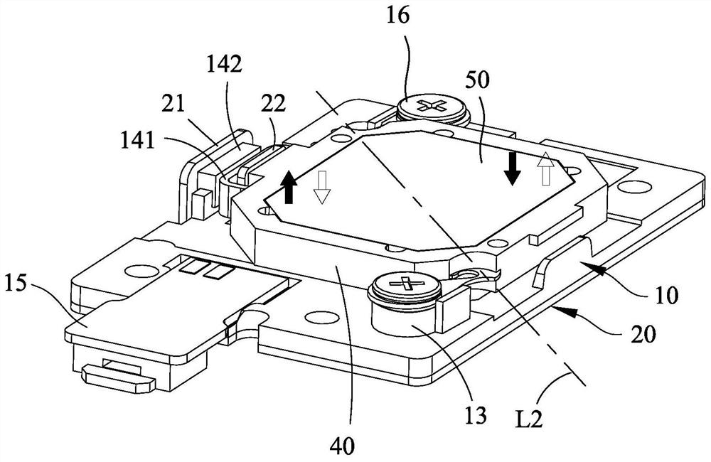
[0051] Please see figure 1 , figure 2 As shown, it is the first embodiment of the application of the suspension system of the single-axis optical actuator of the present invention, which at least includes:

[0052] A base 10 is provided with a square first light-transmitting hole 11 in the center, and on opposite sides of the diagonal line of the first light-transmitting hole 11, a pillar 12, 13 is protruded respectively, and the two pillars 12, 13 13 Positioning marks 121, 131 are provided on one side of the end (the present invention takes positioning tenons as an embodiment), and a positioning baffle 122, 132 is provided on the other side, and the square first light-transmitting hole 11 A set of magnetic devices 14 (composed of coils and magnets) is arranged beside a long side of the base 10, and a connector 15 is arranged at the end of the base 10.

[0053] A reinforcement frame 20, preferably metal, is located under the base 10, and is provided with a second light-tra...


PUM


Abstract

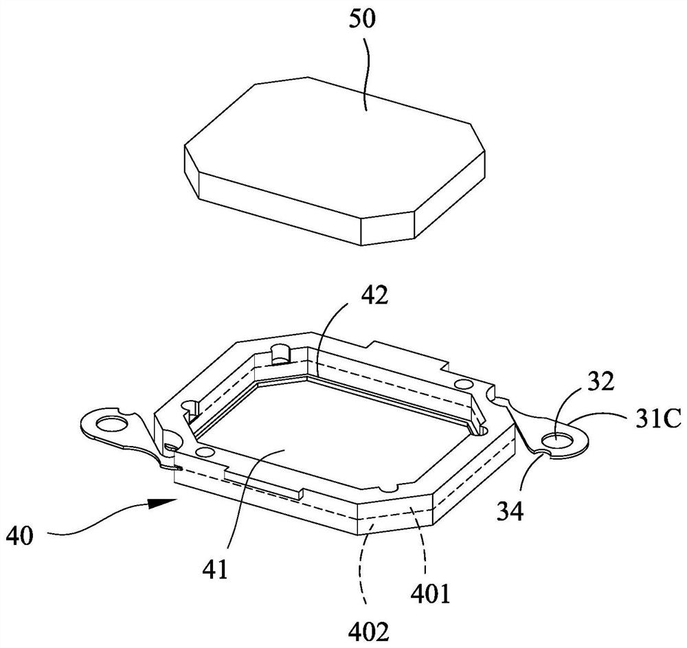
The present invention provides a suspension system for a single-axis optical actuator, which is mainly provided with a frame-shaped suspension shrapnel, and a cantilever protrudes from two opposite ends respectively through a cutting edge and a turning portion, and one side of the suspension shrapnel It is equipped with a magnetic device, and at the same time, it is mounted on a reinforcing frame by a cantilever, which can carry an optical lens. When the actuator is connected to the magnetic device with a current through the connector, it can generate repeated adsorption on one side of the suspended shrapnel. Or repulsive force, so that the suspension shrapnel itself becomes a swinging piece, and at the same time, taking the virtual axis between the two turning parts on the frame as the axis, it carries the optical lens to produce rapid limited swing on both sides.

Description

technical field [0001] The invention relates to a suspension system of a single-axis optical actuator, in particular to a suspension system suitable for a micro-optical actuator of a projection device, which has a swing characteristic in a single-axis direction and can make the actuator The swing is more stable and accurate, greatly improving the resolution and stability of projection. Background technique [0002] The more advanced optical projection system is not only required to be compact in size, but also to have better projection resolution and lower cost. Under these three prerequisites, the current design of the more advanced optical projection system, please refer to Figure 11 , Figure 12 As shown, the image of the microchip panel 92 (for example: DMD) is projected to the projection screen (not shown in the figure) through the prism 91, the actuator 80, and the lens 90; The lens in the device 80, and performs rapid and repeated vibrations (changing the projection...

Claims


Application Information

Patent Timeline
Patent Type & Authority Patents(China)
IPC IPC(8): G03B21/14
CPCG03B21/142
Inventor 赵金生叶世博庄清轩赖韦龙
Owner MIN AIK TECH
Why Eureka
Eureka Blog
Learn More