Olfaction diagnostic apparatus and operation control method thereof

A diagnostic instrument and olfactory technology, applied in the field of olfactory diagnostic instrument and its operation control, can solve problems such as poor diagnostic effect of olfactory diagnostic scheme

Inactive Publication Date: 2020-02-07
江苏金森海默生物技术有限公司
View PDF5 Cites 0 Cited by
  • Summary
  • Abstract
  • Description
  • Claims
  • Application Information

AI Technical Summary

Problems solved by technology

[0003] In view of this, the present application provides an olfactory diagnostic instrument and its operation cont

Method used


Image

  • Olfaction diagnostic apparatus and operation control method thereof
  • Olfaction diagnostic apparatus and operation control method thereof
  • Olfaction diagnostic apparatus and operation control method thereof

Examples


Embodiment 1

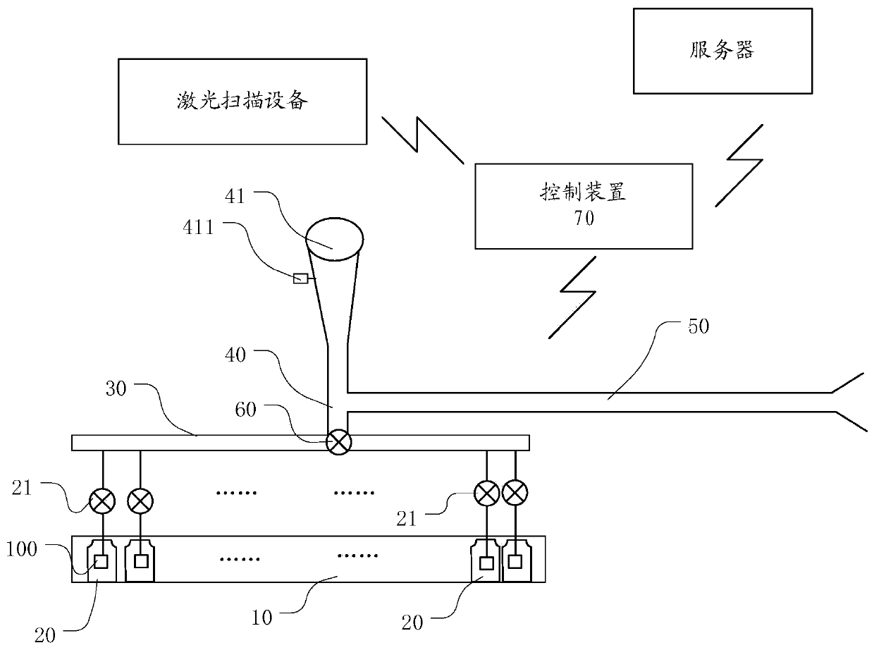
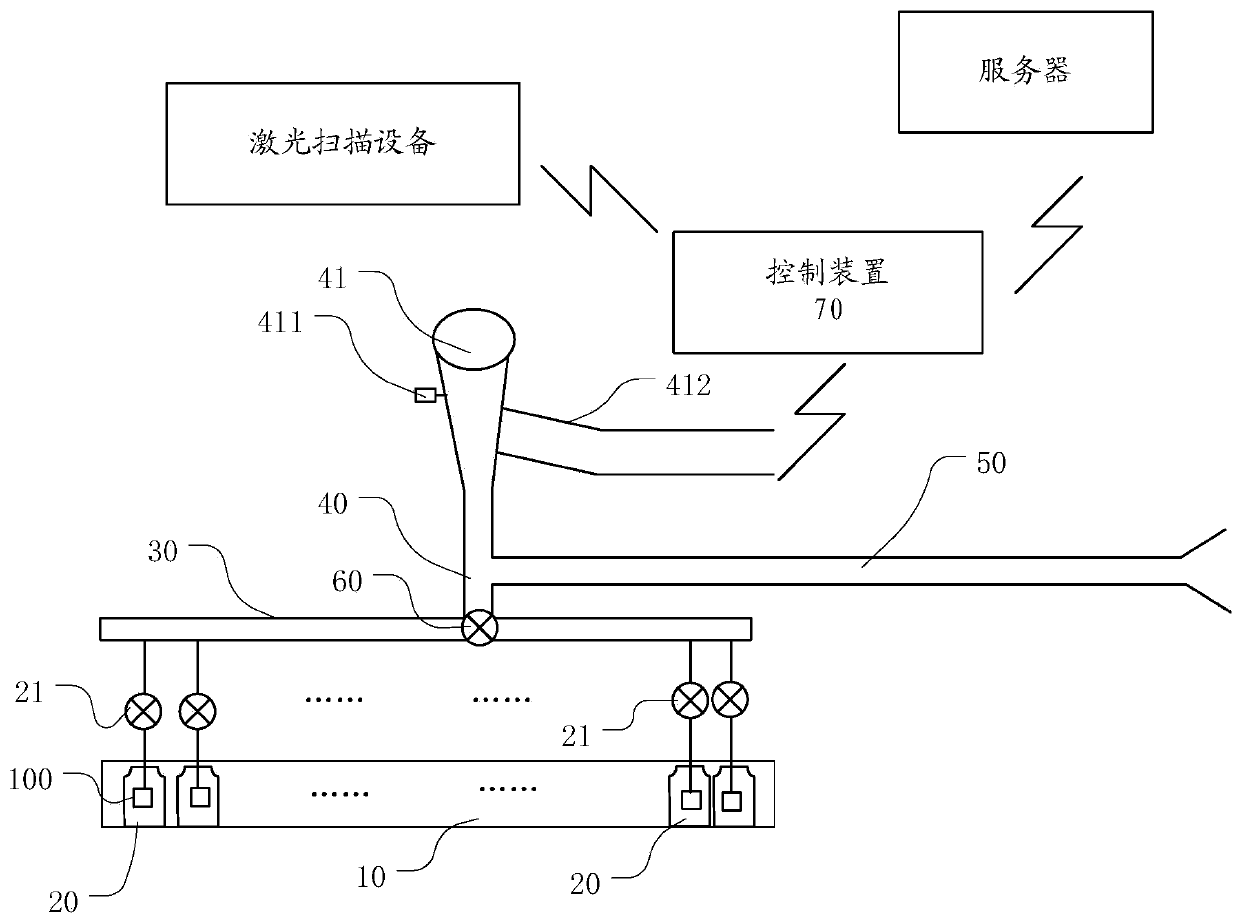
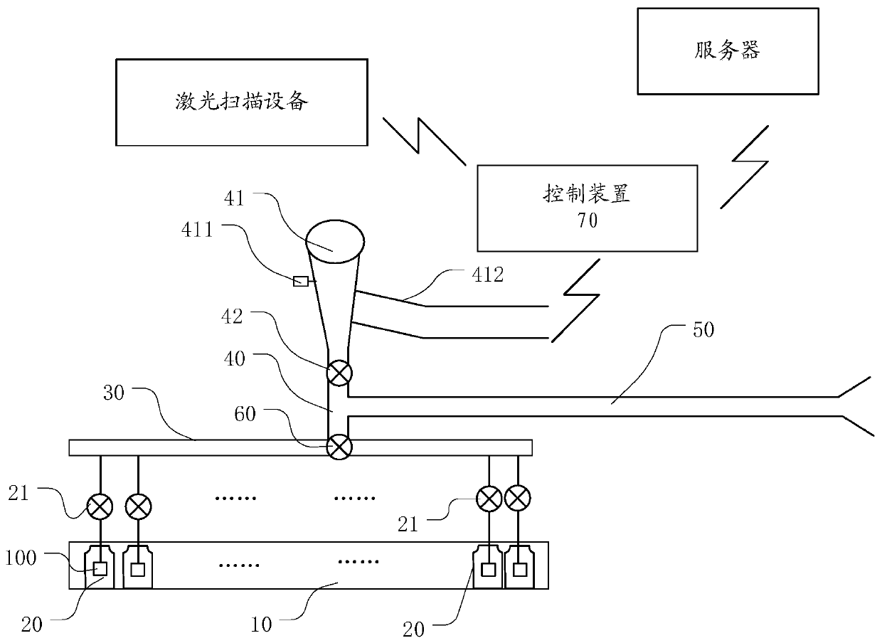
[0052] figure 1 It is a schematic structural diagram of an olfactory diagnostic instrument according to an embodiment of the present application.

[0053] Such as figure 1 As shown, the olfactory diagnostic instrument of this embodiment includes a reagent box 10 , a plurality of reagent bottles 20 , an atomizing vibrator 100 , a total sampling pipeline 30 , a sampling chamber 40 , an emptying pipeline 50 , a sampling air pump 60 and a control device 70 .

[0054] There are multiple slot-shaped compartments in the kit, which can be called placement slots, which are used to place corresponding reagent bottles. Each reagent bottle is connected to the total sampling pipeline through a corresponding pipeline, and each pipeline is provided with a Corresponding solenoid valves, in order to distinguish them from other solenoid valves, the solenoid valve arranged on the pipeline for connecting the reagent bottle and the main sampling pipeline is called the first solenoid valve 21 .

...

Embodiment 2

[0075] Figure 7 It is a flow chart of an operation control method in an embodiment of the present application.

[0076] The operation control method provided in this embodiment is applied to an olfactory diagnostic instrument. The olfactory diagnostic instrument includes a reagent box, a plurality of reagent bottles, a total sampling pipeline, a sampling chamber, an emptying pipeline, a sampling air pump and a control device.

[0077] There are multiple slot-shaped compartments in the kit, which can be called placement slots, which are used to place corresponding reagent bottles. Each reagent bottle is connected to the total sampling pipeline through a corresponding pipeline, and each pipeline is provided with a Corresponding solenoid valves, in order to distinguish them from other solenoid valves, the solenoid valves arranged on the pipeline for connecting the reagent bottles and the main sampling pipeline are called first solenoid valves.

[0078] The atomizing vibrator i...


PUM


Abstract

The invention discloses an olfaction diagnostic apparatus and an operation control method thereof. The olfaction diagnostic apparatus comprises a kit, a plurality of reagent bottles, a plurality of atomization vibrators, a main sampling pipeline, a sampling chamber, an emptying pipeline, a sampling air pump and a control device. The plurality of reagent bottles are arranged in the placement groovein the kit and are communicated with the main sampling pipeline through a first electromagnetic valve; an atomization vibrator is arranged in each reagent bottle; the sampling chamber is communicatedwith the main sampling pipeline and is provided with a nose pad; one end of the emptying pipeline is communicated with the sampling chamber, and the other end of the emptying pipeline is communicatedwith the outside of a diagnosis chamber; the control device is in signal connection with each first electromagnetic valve and is used for controlling the corresponding first electromagnetic valve andthe sampling air pump to be opened or closed according to a control instruction input by a user. According to the scheme, the reagent steam enters the sampling chamber from the reagent bottle throughthe main sampling pipeline is provided for a person to-be-detected for detection and is discharged out of the chamber, so that indoor air cannot be polluted, and the detection effect is improved.

Description

technical field [0001] The present application relates to the technical field of medical devices, and more specifically, to an olfactory diagnostic instrument and its operation control method. Background technique [0002] Smell diagnosis is a routine inspection item in medical diagnosis and physical examination, which is used to check the patient's sense of smell ability. At present, when olfactory diagnosis is performed on a patient, a diagnostic card or a diagnostic bottle is generally used for diagnosis. The diagnostic card is dipped with a reagent of a corresponding taste, and the diagnostic bottle is generally an ordinary reagent bottle containing a reagent of a corresponding taste. However, in actual use, whether it is a diagnostic card or a diagnostic bottle, it needs to emit a corresponding smell in the air to achieve the purpose of diagnosis, so it will pollute the diagnostic environment, so that the diagnostic environment is full of various smells, thus lead to p...

Claims


Application Information

Patent Timeline
IPC IPC(8): A61B5/00
CPCA61B5/4011
Inventor 程海新郑朋
Owner 江苏金森海默生物技术有限公司
Why Eureka
Try Eureka