Manual aspirator and manual sucking method
A technology of suction device and suction tube, which is applied in the field of medical equipment to achieve the effect of convenient operation
- Summary
- Abstract
- Description
- Claims
- Application Information
AI Technical Summary
Problems solved by technology
Method used
Image
Examples
Embodiment 1
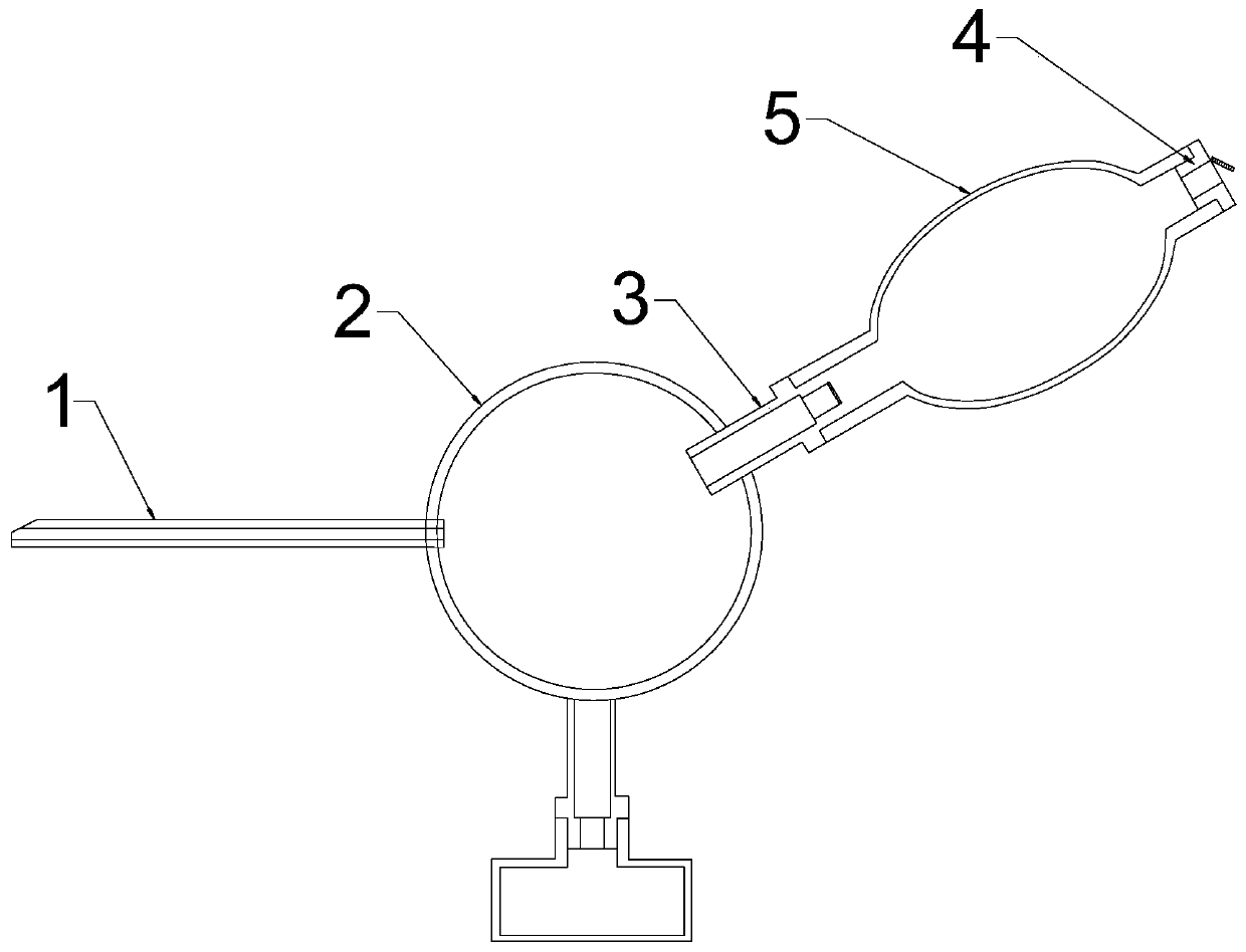
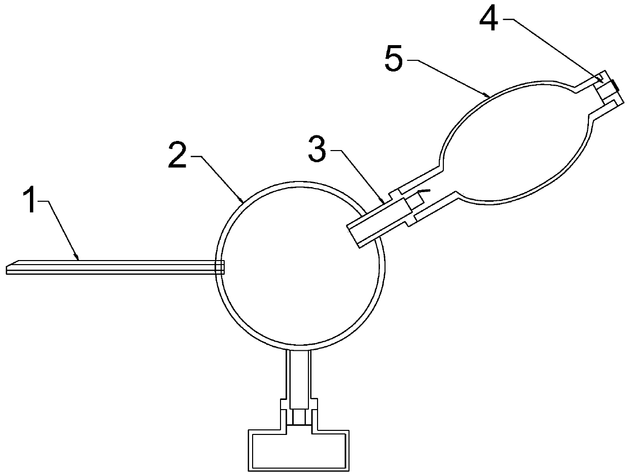
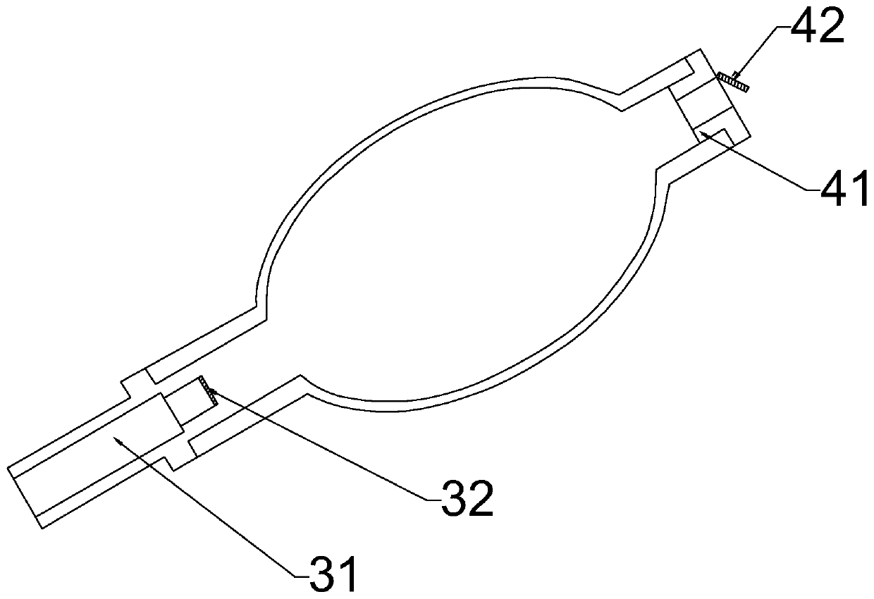
[0043] like figure 1 and figure 2 As shown, the present embodiment provides a manual aspirator, comprising:
[0044] A suction tube 1, one end of the suction tube 1 is formed with a suction end for sucking the substance to be sucked;
[0045]Wherein the suction tube 1 can extend into the patient's chest cavity, abdominal cavity, and airway so that its suction end can be close to or directly contact with materials such as sputum, pus, and blood to be sucked out.
[0046] A transfer chamber 2, the transfer chamber 2 is internally formed with an accommodating space for accommodating the substance to be sucked, and the accommodating space communicates with the end opposite to the suction end of the suction tube 1;
[0047] The transfer chamber 2 plays the role of storage and transfer, and is used for temporarily storing liquid and connecting the negative pressure device 5 . Since the transfer chamber 2 is in communication with one end of the suction tube 1, the substance to be...
Embodiment 2
[0065] like Figure 4 As shown, this implementation is further improved on the basis of Embodiment 1. In this embodiment, the manual aspirator includes at least two negative pressure devices 5 that are connected to each other to provide negative pressure for the manual aspirator.
[0066] When the aspirator of the embodiment is in use, the medical staff squeezes one of the negative pressure devices 5 and then releases it, so that the negative pressure device 5 generates a negative pressure environment. During the suction process of the aspirator, due to the air pressure at the suction end, the negative pressure value of the negative pressure device 5 will gradually decrease and tend to zero. At this time, before the negative pressure value of the negative pressure device 5 is reduced to a certain set threshold value, squeeze the remaining certain negative pressure device 5 and release it to replace the previous negative pressure device 5 to provide suction for the suction dev...
Embodiment 3
[0068] like Figure 5 As shown, the manual aspirator in this embodiment also includes a storage chamber 6 connected to the transfer chamber 2 , and the storage chamber 6 is used to receive the aspirated substance sucked into the transfer chamber 2 . Since the absorbed substance entering the transfer chamber 2 through the suction tube 1 exceeds a certain amount, the work of the aspirator will be affected, so it is necessary to transfer the absorbed substance in the transfer chamber 2 from the transfer chamber 2 in time. However, in this embodiment, a storage chamber 6 connected to the transfer chamber 2 is provided to receive the absorbed substance transferred from the transfer chamber 2 . The storage chamber 6 can be connected to the transfer chamber 2 in a detachable manner. When there are too many absorbed substances in the storage chamber 6, the storage chamber 6 is disassembled, and the absorbed substances in the storage chamber 6 are removed before being connected to the ...
PUM
 Abstract
Description
Claims
Application Information
 - R&D Engineer
- R&D Manager
- IP Professional
- Industry Leading Data Capabilities
- Powerful AI technology
- Patent DNA Extraction
Browse by: Latest US Patents, China's latest patents, Technical Efficacy Thesaurus, Application Domain, Technology Topic, Popular Technical Reports.
© 2024 PatSnap. All rights reserved.Legal|Privacy policy|Modern Slavery Act Transparency Statement|Sitemap|About US| Contact US: help@patsnap.com


