Indoor firefighting robot and work method thereof

A fire extinguishing robot and robot technology, applied in the field of fire extinguishing robots, can solve problems such as economic losses, failure to monitor fires, and loss of life and property, and achieve the effects of reducing economic losses, improving overall control capabilities, and ensuring personal safety

Pending Publication Date: 2020-02-07
QINGDAO BINHAI UNIV
View PDF8 Cites 3 Cited by
  • Summary
  • Abstract
  • Description
  • Claims
  • Application Information

AI Technical Summary

Problems solved by technology

With the increase of modern household electrical products, the frequency of household fires is getting higher and higher. Once a household fire occurs, it is easy to have situations such as untimely extinguishing and lack of fire extinguishing equipment, and the people present are likely to panic and slow down their escape. cause major loss of life and property
Moreover, for high-rise or unoccupied families, when a fire breaks out, it is generally impossible to carry out timely rescue. Even if the firefighters can reach the fire location in time, the fire has spread in a large area, which is likely to cause large damage. Economic losses
[0004] The inventors of the present disclosure have found that although there are some fire-fighting robots currently on the market, most of these robots focus on the identification of flames, which generally have the following problems: (1) In the case of no one on duty, they cannot be effectively and quickly Indoor fire extinguishing can't quickly eliminate the fire in the bud when the fire is small; (2) generally, a robot host is installed indoors, and it is impossible to monitor the fire at multiple easy-to-ignite locations in the room; (3) when a fire occurs In case of emergency, the corresponding power supply and corresponding natural gas equipment cannot be effectively and timely cut off to prevent secondary hazards such as explosions caused by indoor fires.

Method used


Image

  • Indoor firefighting robot and work method thereof
  • Indoor firefighting robot and work method thereof
  • Indoor firefighting robot and work method thereof

Examples


Embodiment 1

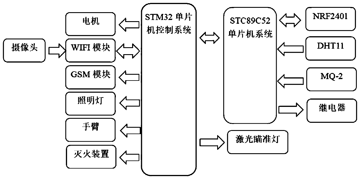
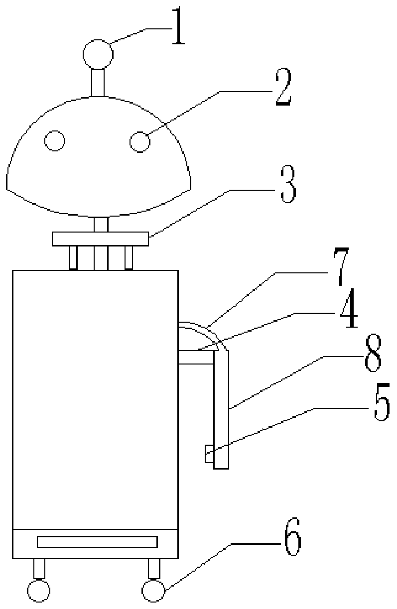
[0047] Such as Figure 1-6 As shown, Embodiment 1 of the present disclosure provides an indoor fire-fighting robot, including at least one robot host and a plurality of robot slaves placed in indoor fire-prone positions, and the robot host includes at least a first microcontroller 15, a fire extinguisher 12 And vision module 2, and described robot host can freely move indoors by universal wheel 6; 3 Realize free rotation in the horizontal direction.

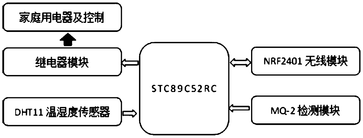
[0048] The first micro-controller adopts the STM32F103ZET6 single-chip microcomputer as the main control chip, and in addition controls the movement of the robot host through the STM32 single-chip microcomputer, and the robot host is also provided with at least a combustible gas sensor, a smoke sensor and a temperature and humidity sensor. The indoor environment is monitored in real time, and at the same time, when a fire occurs, the collected data can be compared and analyzed in real time with the data collected at the fire poi...

Embodiment 2

[0064] Embodiment 2 of the present disclosure provides an indoor fire-fighting robot. When a fire occurs at the positions of multiple robot slaves at the same time, the first micro-controller sends a control command to the robot slave at the indoor general power supply position to turn off the indoor general power supply. At the same time, the first micro-controller judges the distance between each ignition point and the robot host, and quickly moves to the nearest ignition point to put out the fire. Other settings are the same as in Embodiment 1, and will not be repeated here.

Embodiment 3

[0066] Embodiment 3 of the present disclosure provides a working method of an indoor fire extinguishing robot. Using the indoor fire extinguishing robot described in Embodiment 1 or Embodiment 2 of the present disclosure, the steps are as follows:

[0067] Set up at least one robot host and multiple robot slaves placed in indoor fire-prone positions. The robot slaves in the fire-prone positions collect the temperature, humidity and smoke concentration data at the fire-prone positions in real time. When at least one of the collected data is greater than the preset threshold , the second micro-controller controls the relay to cut off the power supply of the electrical equipment corresponding to the ignition point, and sends a fire extinguishing signal to the first micro-controller;

[0068] After the first micro-controller receives the fire extinguishing signal, it controls the robot mainframe to quickly move to the position of the fire point, and uses the vision module to identi...


PUM


Abstract

The disclosure provides an indoor firefighting robot and a work method thereof. The indoor firefighting robot comprises at least one robot host and a plurality of robot slaves placed on indoor positions which easily catch fire, wherein each robot host at least comprises a first microcontroller, a fire extinguisher and a visual module, the robot slaves are connected with power sources of electric devices on the corresponding positions which easily catch the fire in a communication mode, and the at least one robot host is connected with the robot slaves in a wireless communication mode. When fire hazards occur on the positions where the robot slaves are located, the robot salves quickly cut off the power sources of the electric devices on the positions of corresponding ignition points, and send firefighting signals to the first microcontroller, the at least one robot host quickly moves to the positions of the ignition points, and identifies the ignition points through the at least one visual module, and the at least one fire extinguisher is opened for firefighting after the at least one robot host confirms that the fire hazards really occur on the ignition points. The indoor firefighting robot can realize key monitoring for a plurality of the ignition points indoors, effectively extinguishes the fire hazards in a sprouting state, greatly reduces economic loss caused the fire hazards, and improves overall situation control ability for the fire hazards.

Description

technical field [0001] The present disclosure relates to the technical field of fire-fighting robots, in particular to an indoor fire-fighting robot and a working method. Background technique [0002] The statements in this section merely provide background information related to the present disclosure and may not necessarily constitute prior art. [0003] In recent years, the economic losses and casualties directly caused by fires have been increasing, especially the frequent occurrence of family fire accidents. Current household fire extinguishing mainly relies on hand-held fire extinguishers, which generally require manual operation. With the increase of modern household electrical products, the frequency of household fires is getting higher and higher. Once a household fire occurs, it is easy to have situations such as untimely extinguishing and lack of fire extinguishing equipment, and the people present are likely to panic and slow down their escape. result in seriou...

Claims


Application Information

Patent Timeline
Patent Type & Authority Applications(China)
IPC IPC(8): A62C27/00A62C37/00
CPCA62C27/00A62C37/04
Inventor 陈立刚邸改刘桂萍
Owner QINGDAO BINHAI UNIV
Why Eureka
Try Eureka