Annular thin-walled part shape correcting tool and shape correcting and rubber pouring method

A thin-walled part, shape correction technology, applied in the field of glue filling of parts, can solve the problems of difficult cleaning and shape correction of glue filling equipment, and achieve the effect of uniform internal structure of the colloid, reducing surface damage, and not easy to expand and deform.

Active Publication Date: 2020-02-07
AECC AERO SCI & TECH CO LTD
View PDF6 Cites 4 Cited by
  • Summary
  • Abstract
  • Description
  • Claims
  • Application Information

AI Technical Summary

Problems solved by technology

[0005] The object of the present invention is to provide a kind of tooling for correcting the shape of annular thin-walled parts and a method for correcting the shape and pouring glue. Correct the shape of the parts while filling the glue, solve the problem of difficult shape correction of thin-walled ring parts before glue filling, and facilitate demoulding. Bubble problem and the problem of difficult cleaning of glue filling equipment, high-quality glue filling products can be obtained through the shape correction tooling, shape correction and glue filling method

Method used


Image

  • Annular thin-walled part shape correcting tool and shape correcting and rubber pouring method
  • Annular thin-walled part shape correcting tool and shape correcting and rubber pouring method
  • Annular thin-walled part shape correcting tool and shape correcting and rubber pouring method

Examples


Embodiment 1

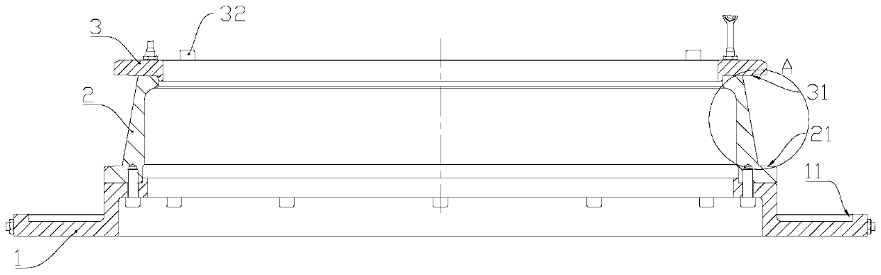
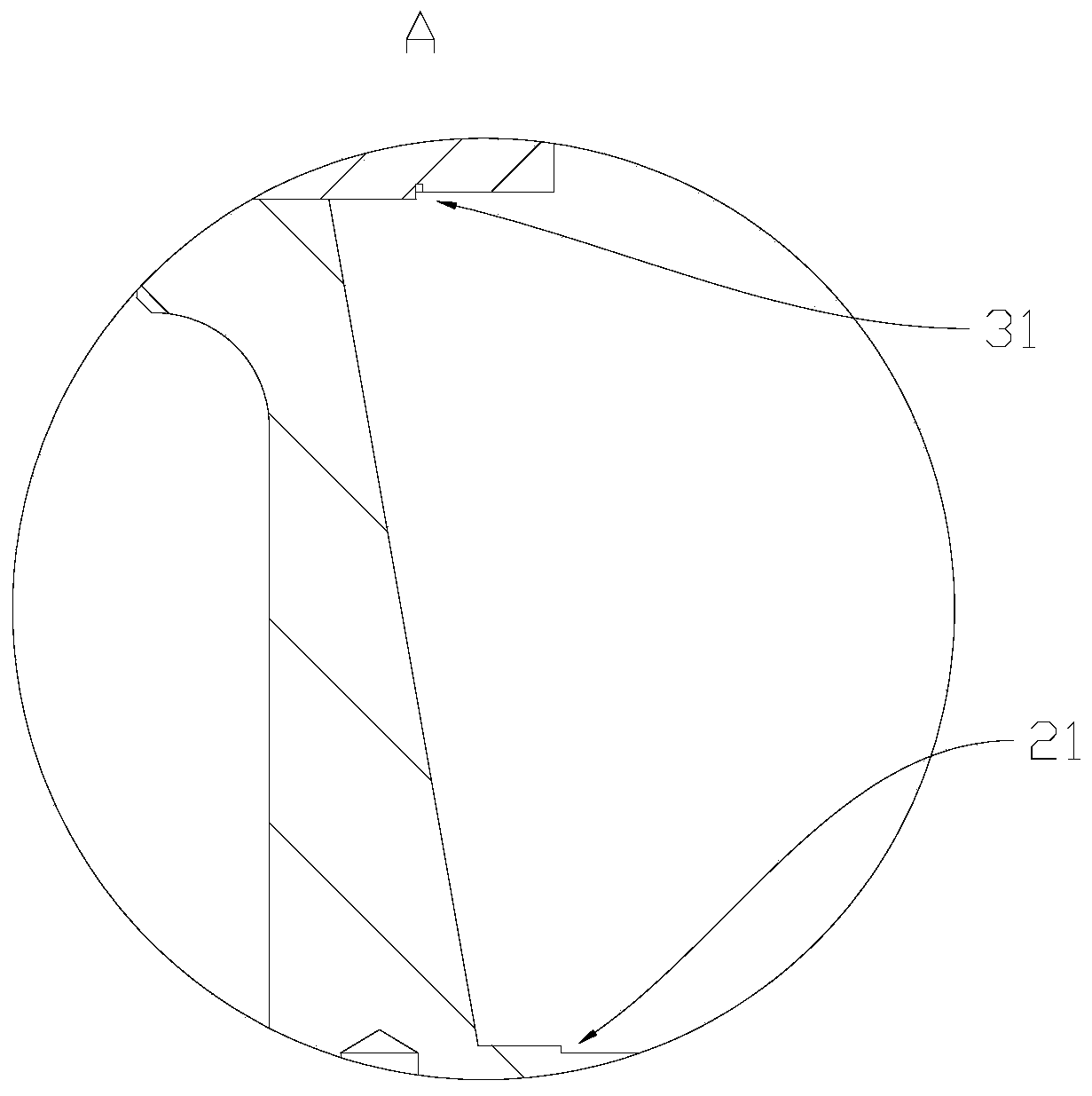
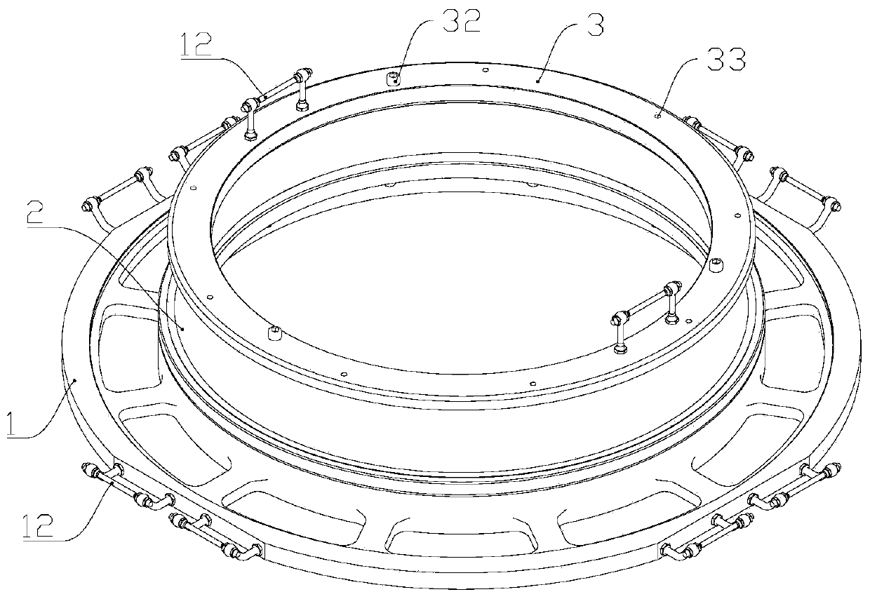
[0044] refer to figure 1 , an annular thin-walled part shape correction tool, comprising: a base 1, a positioning seat 2 and a positioning cover 3, the base 1 and the positioning cover 3 are respectively detachably arranged at both ends of the positioning seat 2, the base 1 and the positioning seat 2 is a cylindrical structure of a rotating body, and the positioning cover plate 3 is an annular plate-shaped structure, refer to figure 2 The bottom surface of the positioning cover plate 3 is provided with a first positioning female notch 31, the base 1, the positioning seat 2 and the positioning cover plate 3 are concentrically arranged, and the bottom ends of the base 1 and the positioning seat 2 are provided with outwardly protruding outer edges, refer to figure 2 , the outer edge of the positioning seat 2 is provided with a second positioning female notch 21, refer to figure 1, the outer edge of the base 1 is provided with a third positioning female notch 11, the positioni...

Embodiment 2

[0061] The difference between this embodiment and Embodiment 1 is that in step c of the glue liquid vacuum defoaming of the annular thin-walled part shape correction and glue pouring method, the vacuum defoaming pressure is 4.5KPa, the vacuum defoaming time is 20min, and the degassing 3 times; in step e curing and shaping, place the parts filled with glue at room temperature for 14 hours, and then heat and cure. The curing temperature is 100°C and the curing time is 1.3 hours.

Embodiment 3

[0063] The difference between this embodiment and Embodiment 1 and Embodiment 2 is that in step c of the glue solution vacuum defoaming in the shape correction of the annular thin-walled parts and the glue pouring method, the vacuum defoaming pressure is 4KPa, and the vacuum defoaming time is 25min , degassing 4 times; in step e curing and shaping, place the filled parts at room temperature for 15 hours, and then heat and cure. The curing temperature is 105°C and the curing time is 1 hour.


PUM


Abstract

The invention discloses an annular thin-walled part shape correcting tool and a shape correcting and rubber pouring method, and belongs to the technical field of part rubber pouring. The annular thin-walled part shape correcting tool comprises a base, a positioning seat and a positioning cover plate; the base and the positioning cover plate are detachably arranged at the two ends of the positioning seat; the base and the positioning seat are each of a rotation body cylindrical structure, and the positioning cover plate is of an annular plate-like structure; the base, the positioning seat and the positioning plate are concentrically arranged; the bottom end of the base and the bottom end of the positioning seat are both provided with outer edges protruding outwards; and the side surface ofthe positioning cover plate, the side surface of the positioning seat and the outer edge of the positioning seat form an inner ring shape correcting groove for a part, and the outer edge of the base and the side surface of the base form an outer ring positioning shape correcting groove for the part. The shape correcting and rubber pouring method for an annular thin-walled part comprises the stepsof shape pre-correcting, rubber liquid vacuum defoaming, rubber pouring and solidification, shape setting and the like. Through the shape correcting tool and the processing method, the size and shapeof the rubber pouring part and the inner quality of the rubber can be sufficiently ensured, and accordingly, a high-quality rubber poured product can be obtained.

Description

technical field [0001] The invention relates to the technical field of glue filling of parts, in particular to a shape-calibrating tool of an annular thin-walled part and a shape-calibrating and glue-filling method. Background technique [0002] Room temperature vulcanized silicone rubber is a silicone rubber modified by adding hollow glass microspheres. Compared with ordinary silicone rubber, the modified silicone rubber has reduced elasticity, better mechanical properties, and better processability. Fine machining needs. At present, room temperature vulcanized silicone rubber is mainly used in the supercharged stator components of military and civilian high-pass ratio aero-engines. After the perfused colloid is cured, the stator blades are glued to the leaf-shaped holes of the inner ring of the stator to form the inner ring sealing surface. It plays the role of fixing and damping the stator blades. At the same time, after the colloid is vulcanized, it can be machined to a...

Claims


Application Information

Patent Timeline
Patent Type & Authority Applications(China)
IPC IPC(8): B21D3/14B21D53/16B29C39/10B29B13/00B29C39/24
CPCB21D3/14B21D53/16B29B13/00B29B2013/005B29C39/10B29C39/24B29L2031/7102
Inventor 李洪钊黎红英石思琪谷平陈秋娟黄建军
Owner AECC AERO SCI & TECH CO LTD
Why Eureka
Try Eureka