Automatic cutting and blanking equipment for steel pipe joint long pipe

A steel pipe joint and automatic cutting technology, applied in shearing machine equipment, metal processing equipment, pipe cutting devices, etc., can solve the problems of frequent disassembly, low work efficiency, high cost of cutting and processing steel pipe joints and long pipes, and reduce the labor of workers. Strength, the effect of improving work efficiency

Pending Publication Date: 2020-02-07
济南迈科管道科技有限公司
View PDF0 Cites 0 Cited by
  • Summary
  • Abstract
  • Description
  • Claims
  • Application Information

AI Technical Summary

Problems solved by technology

[0002] The long pipe blanking of steel pipe joints usually refers to the long pipe blanking of 450㎜-6400㎜ steel pipe joints. At present, the long pipe blanking of steel pipe joints is mostly manually squeezed and blanked by one person and one machine, and the original steel pipe is manually placed at the rear of the blanking machine Through the hollow shaft, it is sent to the extrusion and blanking place of the equipment. Manually clamp the original steel pipe with a three-jaw chuck, turn on the main shaft, and then manually push the extrusion tool to cut off the original steel pipe. Since the original pipe length of the steel pipe is 6400 ㎜, sometimes the cutting length of the steel pipe joint long pipe is long, and the original pipe of the steel pipe is clamped once and several pieces of the steel pipe joint long pipe are cut off to complete the cutting of the original steel pipe. , the steel pipe joint long pipe blanking, clamping and disassembly are particularly frequent, the labor intensity of the processing workers is high, the steel pipe joint long pipe blanking processing cost is high, and the work efficiency is low

Method used


Image

  • Automatic cutting and blanking equipment for steel pipe joint long pipe
  • Automatic cutting and blanking equipment for steel pipe joint long pipe
  • Automatic cutting and blanking equipment for steel pipe joint long pipe

Examples


Embodiment 1

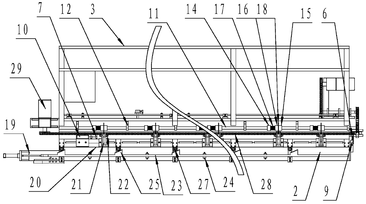
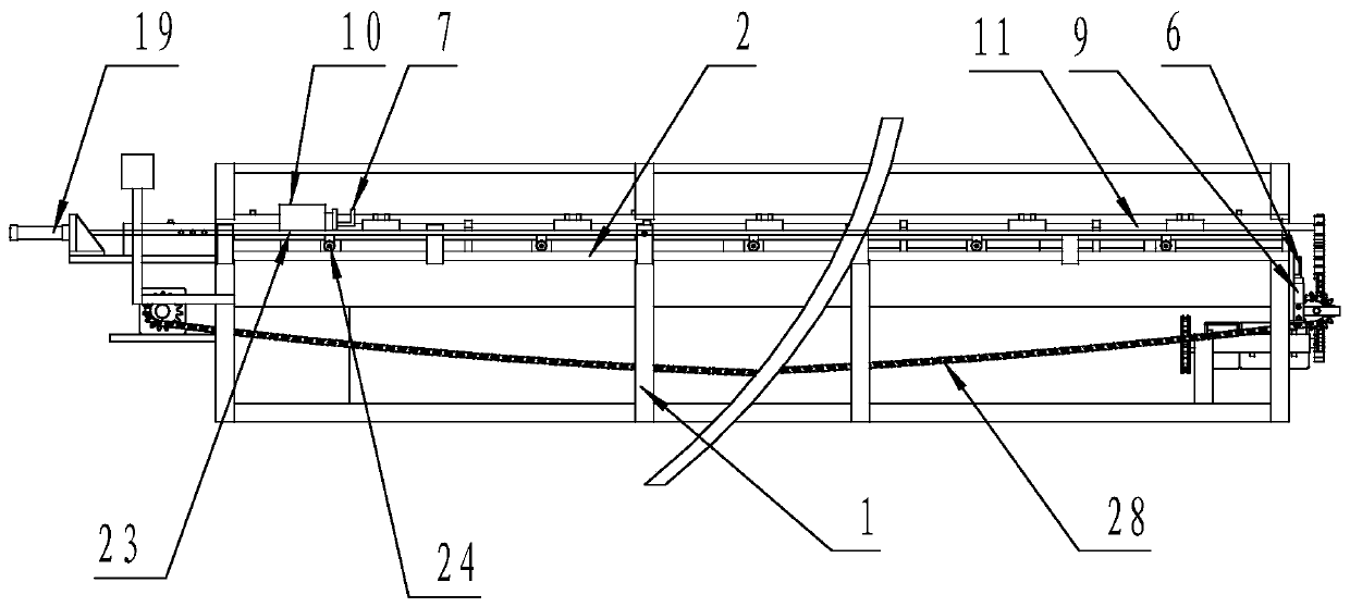
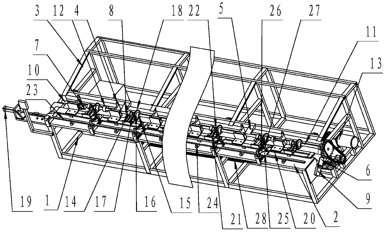
[0021] Such as figure 1 , figure 2 , image 3 As shown, an automatic cutting and blanking equipment for long steel pipe joints, including a hollow bar rack 1, a bar workbench 2 installed on the top surface of the hollow bar rack 1, and a rear side installation of the hollow bar rack 1 The original steel pipe storage bracket 3 with an inclined top surface is characterized in that: the original steel pipe storage bracket 3 with an inclined top surface is adjacent to the hollow strip frame 1 and is successively provided with vertical 7 bar-shaped baffles 4 that block the sliding of the steel pipe original pipe (the operator faces the invention, the left side of the operator is the left side of the hollow bar-shaped rack, and the right side of the operator is the right side of the hollow bar-shaped rack; close to the operator The side of the operator is the front side of the bar-shaped workbench, and the side away from the operator is the back side of the bar-shaped workbench),...


PUM


Abstract

The invention discloses automatic cutting and blanking equipment for a steel pipe joint long pipe. The automatic cutting and blanking equipment for the steel pipe joint long pipe comprises a hollow strip-shaped machine frame, a strip-shaped workbench, a steel pipe raw pipe storage support with an inclined top surface and at least seven strip-shaped baffles, and further comprises an automatic steelpipe raw pipe feeding device, automatic steel pipe raw pipe positioning devices, a steel pipe joint long pipe extrusion blanking device and an automatic steel pipe joint long pipe output device, wherein the automatic steel pipe raw pipe positioning devices are arranged on the two sides of the hollow strip-shaped machine frame, the steel pipe joint long pipe extrusion blanking device is arranged on the strip-shaped workbench, and the automatic steel pipe joint long pipe output device is arranged on the hollow strip-shaped machine frame. According to the equipment, automatic feeding and automatic positioning of a steel pipe raw pipe are realized, the labor intensity of workers for steel pipe joint long pipe blanking and the processing production cost for steel pipe joint long pipe blankingare lowered, and the steel pipe joint long pipe blanking working efficiency is improved.

Description

technical field [0001] The invention belongs to a steel pipe cutting and blanking device, in particular to a steel pipe joint long pipe automatic cutting and blanking device. Background technique [0002] The long pipe blanking of steel pipe joints usually refers to the long pipe blanking of 450㎜-6400㎜ steel pipe joints. At present, the long pipe blanking of steel pipe joints is mostly manually squeezed and blanked by one person and one machine, and the original steel pipe is manually placed at the rear of the blanking machine Through the hollow shaft, it is sent to the extrusion and blanking place of the equipment. Manually clamp the original steel pipe with a three-jaw chuck, turn on the main shaft, and then manually push the extrusion tool to cut off the original steel pipe. Since the original pipe length of the steel pipe is 6400 ㎜, sometimes the cutting length of the steel pipe joint long pipe is long, and the original pipe of the steel pipe is clamped once and several ...

Claims


Application Information

Patent Timeline
IPC IPC(8): B23D21/00B23D33/00
CPCB23D21/00B23D33/00
Inventor 王保峰刘培安刘孟伟孔令国
Owner 济南迈科管道科技有限公司
Why Eureka
Try Eureka