
Auxiliary fixing device for electric permanent-magnet workbench

A fixing device and electro-permanent magnet technology, which is applied in the field of mechanical processing, can solve the problems of damaging the electro-permanent magnet table, and achieve the effects of easy cleaning, avoiding damage, and avoiding direct contact

Pending Publication Date: 2020-02-07
浙江合兴电工有限公司
View PDF0 Cites 4 Cited by
  • Summary
  • Abstract
  • Description
  • Claims
  • Application Information

AI Technical Summary

Problems solved by technology

[0003] Therefore, the technical problem to be solved by the present invention is to overcome the defect that the electro-permanent magnet table will be damaged when the workpiece is processed by the electro-permanent magnet table in the prior art, thereby providing an auxiliary fixing device for the electro-permanent magnet table

Method used


Image

  • Auxiliary fixing device for electric permanent-magnet workbench
  • Auxiliary fixing device for electric permanent-magnet workbench
  • Auxiliary fixing device for electric permanent-magnet workbench

Examples


specific Embodiment approach

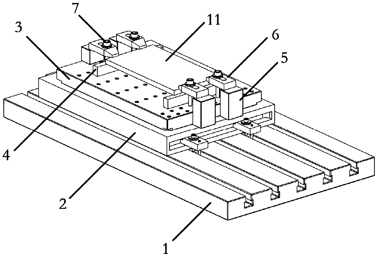
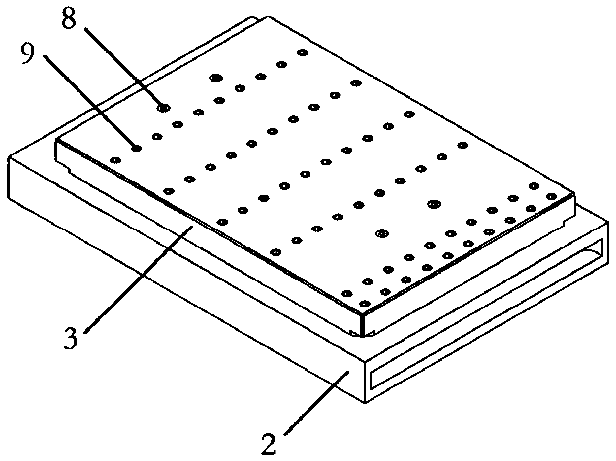
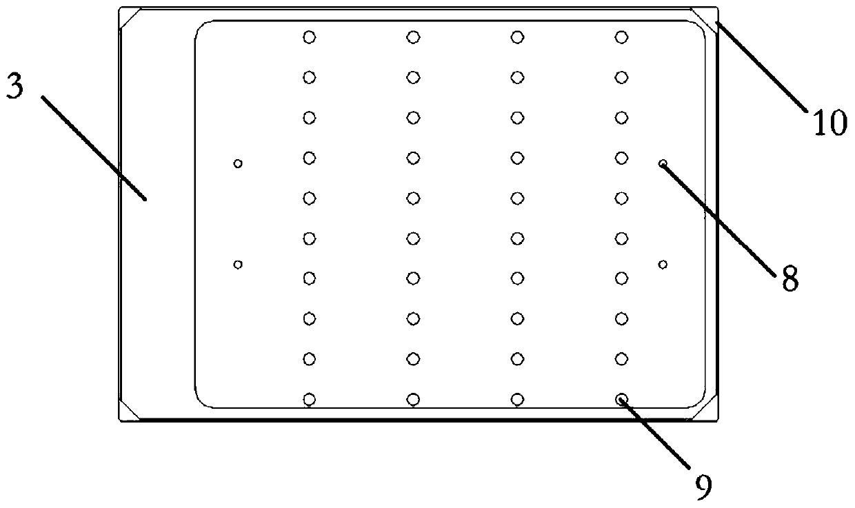
[0033] Such as figure 1 -5 shows a specific implementation of the electric permanent magnet table auxiliary fixing device provided in this embodiment, including: a protective case 3 and a pair of clamping assemblies.

[0034] The bottom surface of the protective shell 3 is provided with a cavity groove, and the protective shell 3 is fixed on the top of the electro-permanent magnetic table 2 through the cavity groove. The top surface of the protective shell 3 is provided with a plurality of first through holes 9, and the plurality of first The through holes 9 are arranged in rows and columns, and the first through holes 9 are threaded holes. The opposite ends of the top surface of the protective case 3 are respectively provided with two second through holes 8, and the four second through holes 8 are respectively fixedly connected with the electro-permanent magnet table 2 by four fixing bolts as the second fasteners. , the fixing bolt is screwed into the threaded hole on the el...


PUM


Abstract

The invention relates to the technical field of machining, in particular to an auxiliary fixing device for an electric permanent-magnet workbench. The auxiliary fixing device for the electric permanent-magnet workbench comprises a protective shell and at least one pair of clamping assemblies, wherein a cavity groove is formed in the bottom surface of the protective shell, the protective shell is cooperatively fixed to the electric permanent-magnet workbench through the cavity groove, and a plurality of through holes are formed in the top surface of the protective shell; and the paired clampingassemblies are separately installed at the two opposite ends of the protective shell to form an installation space of a to-be-machined workpiece, and each clamping assembly at least comprises a firstfastener which is inserted into one through hole to fixedly install the to-be-machined workpiece in the installation space above the protective shell. The protective shell is cooperatively fixed to the electric permanent-magnet workbench through the cavity groove, and meanwhile, the to-be-machined workpiece is fixedly installed by means of the clamping assemblies; and when the workpiece is machined through a machine tool, the protective shell can protect the electric permanent-magnet workbench, and the situation that a milling cutter penetrates through the workpiece and consequentially damages the electric permanent-magnet workbench is prevented.

Description

technical field [0001] The invention relates to the technical field of mechanical processing, in particular to an auxiliary fixing device for an electro-permanent magnetic table. Background technique [0002] Electro-permanent magnet table refers to a magnetic workbench that relies on permanent magnet steel to generate suction, uses excitation coils to control the suction of the magnet steel, and acts as a suction switch. In the process of cutting a workpiece by using a machining center machine tool, in order to improve the machining accuracy of the workpiece, an electro-permanent magnetic table is usually used to fix the workpiece. When the workpiece is directly fixed on the magnetic table, the milling cutter will mill to the electro-permanent magnetic table when processing the through hole, causing damage to the electro-permanent magnetic table. Contents of the invention [0003] Therefore, the technical problem to be solved by the present invention is to overcome the d...

Claims


Application Information

Patent Timeline
Patent Type & Authority Applications(China)
IPC IPC(8): B23Q3/154B23Q3/06B23Q11/08
CPCB23Q3/1543B23Q3/06B23Q11/08
Inventor 林昌乐蒋聪聪陈威特陈洪莉
Owner 浙江合兴电工有限公司
Learn More