Hot melt device for producing thermoplastic polyurethane elastomers

A technology for thermoplastic polyurethane and production heat, which is applied in the field of hot-melt devices for thermoplastic polyurethane elastomer production, can solve the problems of long time required for hot-melting and reduce the practicability of the device, and achieves improved convenience, practicability, The effect of improving work efficiency

Inactive Publication Date: 2020-02-07
NANTONG DE NEW MATERIAL CO LTD
View PDF3 Cites 2 Cited by
  • Summary
  • Abstract
  • Description
  • Claims
  • Application Information

AI Technical Summary

Problems solved by technology

The above-mentioned patent also has the following disadvantages: the material is not crushed, and the larger the volume of the material, the longer the time required for thermal melting, which reduces the practicability of the device

Method used


Image

  • Hot melt device for producing thermoplastic polyurethane elastomers
  • Hot melt device for producing thermoplastic polyurethane elastomers
  • Hot melt device for producing thermoplastic polyurethane elastomers

Examples


Embodiment 1

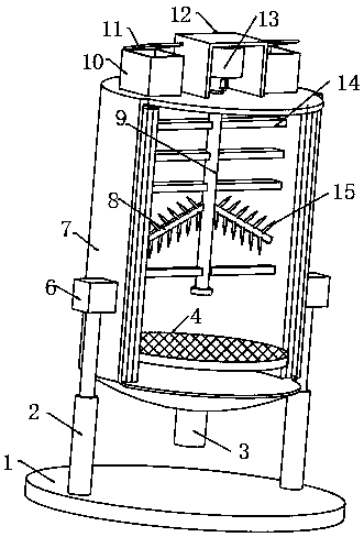
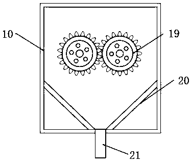
[0029] refer to Figure 1-3 , a thermoplastic polyurethane elastomer production hot-melt device, including a base plate 1, both sides of the top outer wall of the base plate 1 are welded with hydraulic rods 2, and the top outer wall of the hydraulic rod 2 is welded with a fixed block 6, and the outer wall of the fixed block 6 is welded There is a hot melt tank body 7, and the top outer wall of the hot melt tank body 7 is welded with a feed box 10, the top outer wall of the feed box 10 is connected with a heat preservation cover 11 through a hinge, the bottom inner wall of the feed box 10 and the hot melt tank body The top inner wall of 7 is connected with the same feed pipe 21 through a flange, and the bottom inner wall of the feed box 10 is welded with a blanking plate 20 on both sides, and the inner wall of one side of the feed box 10 is connected with a second rotating rod through a bearing. , and the outer wall of the second rotating rod is welded with a crushing roller 19...

Embodiment 2

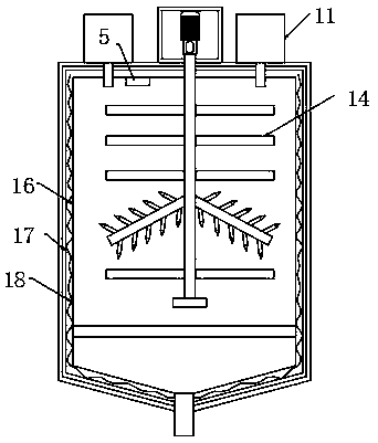
[0033] refer to Figure 4 , a thermoplastic polyurethane elastomer production hot-melt device, also includes a slot 23 welded to the inner wall of the hot-melt tank body 7, the inner wall of the slot 23 is clamped with a block 22, and the top outer wall of the block 22 is fixed by a screw On the top outer wall of the filter plate 4 , the locking groove 23 and the locking block 22 are engaged with each other, which facilitates the installation and removal of the filter plate 4 and improves the convenience of the device.

[0034] Working principle: connect the equipment to the power supply, connect the hydraulic rod 2 to the hydraulic system, adjust the length of the hydraulic rod 2 according to the height of the staff, put the material into the material box 10, turn on the second motor, and use the crushing roller 19 to crush the material , the pulverized material enters the hot melt tank body 7 from the feed pipe 21, the heating wire 18 is turned on, the motor 13 is turned on,...


PUM


Abstract

The invention relates to the field of hot melt devices, and discloses a hot melt device for producing thermoplastic polyurethane elastomers. The device comprises a bottom plate, wherein hydraulic rodsare arranged on two sides of the top outer wall of the bottom plate, and fixed blocks are arranged on the top outer walls of the hydraulic rods; a hot melt tank body is arranged on the outer walls ofthe fixed blocks, and feed boxes are arranged on the top outer wall of the hot melt tank body; insulation covers are connected to the top outer walls of the feed boxes by hinges; a feed pipe is arranged at the bottom inner wall of each feed box and the top inner wall of the hot melt tank body, and discharge plates are arranged on two sides of the bottom inner walls of the feed boxes. The device has the following advantages and effects: the feed boxes, a second motor and crushing rollers are arranged, after materials enter the feed boxes, the second motor is started, the materials are crushedby the crushing rollers, the surface area of the crushed materials is increased, the hot melting speed of the materials can be effectively improved, and working efficiency is improved.

Description

technical field [0001] The invention relates to the technical field of hot-melt devices, in particular to a hot-melt device for producing thermoplastic polyurethane elastomers. Background technique [0002] Thermoplastic polyurethane elastomer is also called thermoplastic polyurethane rubber. Thermoplastic polyurethane rubber is cross-linked by intermolecular hydrogen bonds or slightly cross-linked between macromolecular chains. As the temperature increases or decreases, these two cross-linked structures are reversible. [0003] After searching, the Chinese patent application number is 201821720598.1, which discloses a hot-melt device for the production of thermoplastic polyurethane elastomers, including a box body. The box body is a cylindrical barrel, and the inner wall of the box is provided with a heating plate. The inside of the box body is provided with a stirring device for convection of the material. The present invention improves the existing device and adds a stirr...

Claims


Application Information

Patent Timeline
Patent Type & Authority Applications(China)
IPC IPC(8): B29B13/02B29B13/10B29B7/16B29B7/22B29B7/24B29B7/28
CPCB29B7/16B29B7/22B29B7/24B29B7/286B29B13/022B29B13/10
Inventor 陈乔健
Owner NANTONG DE NEW MATERIAL CO LTD
Why Eureka
Try Eureka