Helical pipeline concrete automatic transport device

An automatic conveying device and concrete technology, applied in the direction of conveyor objects, transportation and packaging, packaging, etc., can solve the problems of splashing, large drop in chute conveying, self-weight, etc., and achieve high safety performance, strong stability and reasonable structure Effect

Pending Publication Date: 2020-02-07
NO 3 ENG LIMITED OF CR20G
View PDF0 Cites 0 Cited by
  • Summary
  • Abstract
  • Description
  • Claims
  • Application Information

AI Technical Summary

Problems solved by technology

[0003] At present, when the concrete is conveyed below the ground level, the chute is generally used, but because the chute conveys a large drop, the stones and mortar mixed into the concrete are free to fall, so it is easy to form the free fall of the mortar and concentrate directly below, while Larger stones are mostly splashed around, which reduces the mixing standard of concrete and seriously affects the strength and quality of concrete construction projects; concrete delivery pumps are generally used to transport concrete when constructing above the ground, and concrete delivery pumps are usually used for concrete needs. Projects with a large amount of use and high construction points are carried out, but because the concrete delivery pump and delivery vehicle are large in size and heavy, transportation and on-site construction are inconvenient, and more importantly, the concrete delivery pump and delivery vehicle cannot be used for horizontal construction Point-to-point concrete delivery
At present, there is no automatic conveying of concrete in the spiral pipeline that can complete the horizontal conveying of concrete, and can also complete the conveying of concrete at 45 degrees above the horizontal level. It can convey not only mixed concrete, but also sand, gravel and cement powder. device

Method used


Image

  • Helical pipeline concrete automatic transport device
  • Helical pipeline concrete automatic transport device

Examples


Embodiment Construction

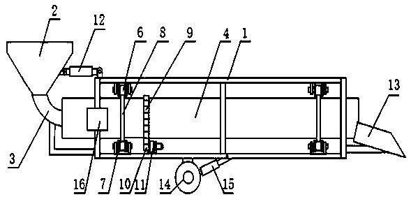
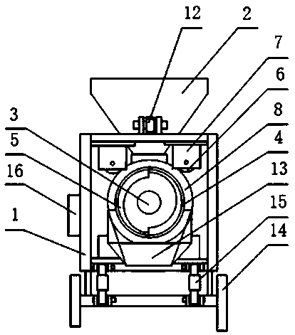
[0011] The present invention will be described in further detail below in conjunction with accompanying drawing:

[0012] The frame 1 is a frame type, and the wheel bases 7 are respectively fixed in the four corners of the two ends of the frame 1, the reducer 11 is installed on the inner bottom of the frame 1 and the driving gear 10 is connected, and the positioning wheels 6 are respectively installed in each wheel base 7, The conveying pipe 3 penetrates into the frame 1 and is fixed between the positioning wheels 6 at the same time. The inner wall of the conveying pipe 3 is provided with two sets of helical blades 5, and its outer edge is fixed with a circular ring 8 and snapped into the groove of the positioning wheel 6. Inside, the outer edge of the conveying pipe 3 corresponding to the driving gear 10 is installed with a ring gear 9 and meshed with it, and the feeding pipe 3 and the feeding hopper 2 are connected through the frame 1 at the left end of the conveying pipe 4, ...


PUM


Abstract

The invention discloses a helical pipeline concrete automatic transport device. The helical pipeline concrete automatic transport device is characterized in that wheel seats, a speed reducer and a drive gear are fixed in a machine frame, a transport pipe is limited and fixed among positioning wheels in the wheel seats, multiple groups of helical blades are arranged on the inner wall of the transport pipe, annular rail rings are fixed on the outer edge of the transport pipe, and clamped in grooves in the positioning wheels, inner rings are installed on a part, corresponding to the drive gear, of the outer edge of the transport pipe, and meshed with one another, a horizontal adjusting lead screw is hinged between a feeding hopper and the machine frame which are connected in a through mode through the transport pipe, a discharging hopper and walking wheels are connected with the part, at the right end of the transport pipe, of the machine frame, and an angle adjusting lead screw is hingedbetween each walking wheel and the machine frame. The helical pipeline concrete automatic transport device not only completes horizontal transport of concrete, but also can complete transport in thedirection at an angle larger than 45 degrees with the horizontal plane, not only can transport the concrete, but also can transport gravels and cement powder materials, saves energy and protects environment, is reasonable in structure, simple and convenient to operate, high in safety performance and strong in stability, overcomes the defects existing in existing leakage groove and concrete delivery pump transport, and can completely accord with quality and safety requirements.

Description

technical field [0001] The invention relates to a concrete conveying device, in particular to a spiral type pipeline concrete automatic conveying device, which belongs to the field of construction machinery. Background technique [0002] With the rapid development of infrastructure such as highways and urban subways, a large amount of concrete needs to be used in the construction of road and bridge tunnels and bridge piers, underground abutments, culverts, retaining walls, etc. Pour quality. [0003] At present, when the concrete is transported below the ground level, the chute is generally used. However, due to the large drop in the chute, the stones and mortar mixed into the concrete are free to fall, so it is easy to form the free fall of the mortar and concentrate directly below. Larger stones are mostly splashed around, which reduces the mixing standard of concrete and seriously affects the strength and quality of concrete construction projects; concrete delivery pumps...

Claims


Application Information

Patent Timeline
Patent Type & Authority Applications(China)
IPC IPC(8): B65G33/24B65G33/26B65G33/34B65G47/34B65G41/00
CPCB65G33/24B65G33/26B65G33/34B65G41/00B65G47/34
Inventor 马小利冯建军吕剑郁海江李光军庄乾理王云鹏车亚奎吴秀成冯钰
Owner NO 3 ENG LIMITED OF CR20G
Why Eureka
Try Eureka