Connection structure for prefabricated integral bay window, and assembling method thereof

A technology for connecting structures and bay windows, applied in building structures, buildings, etc., can solve the problems of small on-site operation tolerance and adjustable range, high production precision requirements for prefabricated components, and difficulty in grouting compactness detection. The effect of high mold turnover, high demoulding efficiency and lower construction cost

Active Publication Date: 2020-02-07
CHINA MINGSHENG DRAWIN TECH INVESTMENT CO LTD
View PDF7 Cites 8 Cited by
  • Summary
  • Abstract
  • Description
  • Claims
  • Application Information

AI Technical Summary

Problems solved by technology

This connection method needs to extend the pre-embedded bolts in multiple beams into the pre-embedded grouting sleeve in the bay window at the same time, which requires high production precision of prefabricated components, and the field operation tolerance and adjustable range are very small; In the manufacturing stage, due to the unevenness of the PC parts, the cost of the mold is high, and the pre-embedding efficiency is low; in the construction stage, the cost of grouting is high, and it is difficult to detect the density of grouting

Method used


Image

  • Connection structure for prefabricated integral bay window, and assembling method thereof
  • Connection structure for prefabricated integral bay window, and assembling method thereof
  • Connection structure for prefabricated integral bay window, and assembling method thereof

Examples


Embodiment 1

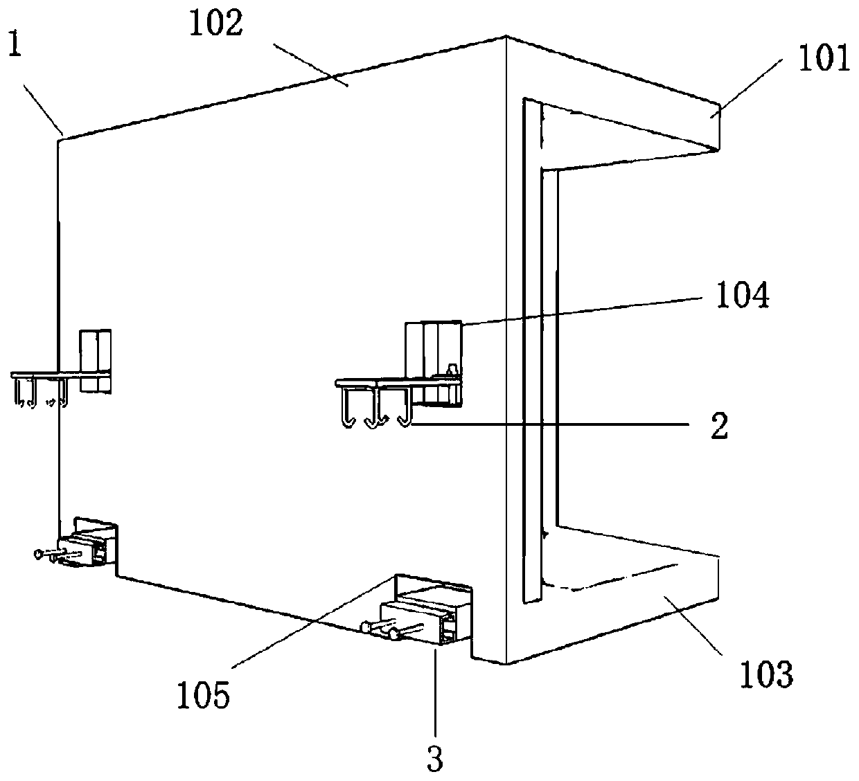
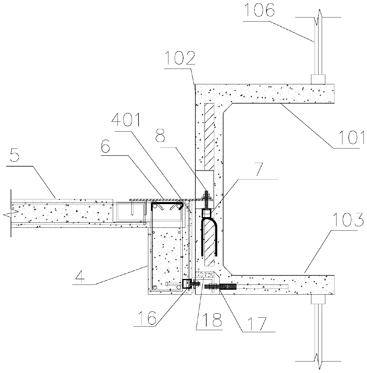
[0051] See attached figure 2 As shown, the connection structure of the prefabricated integral bay window 1 in this embodiment includes the prefabricated integral bay window 1 and the composite beam 4, wherein the composite beam 4 includes a prefabricated part and a cast-in-place part. See attached figure 1 As shown, the prefabricated integral bay window 1 is integrally cast into a C-like shape, including a top plate 101, a side wall 102 and a bottom plate 103, wherein a groove 104 is arranged on the indoor side of the side wall 102, and an upper connection assembly 2 is arranged at the groove 104; A notch 105 for accommodating the box is provided at the intersection of the side wall 102 and the bottom plate 103 , and the lower connection assembly 3 is provided at the notch 105 . See attached figure 2 As shown, the bottom surface of the bottom plate 103 of the prefabricated integral bay window 1 is located at the same level as the bottom surface of the prefabricated part. ...

Embodiment 2

[0068] The connection structure of the prefabricated integral bay window 1 in this embodiment differs from that in Embodiment 1 in that the specific structural forms of the upper connection assembly 2 and the lower connection assembly 3 are different. Wherein, the connection part 6 of the upper connection assembly 2 is the same as that in the first embodiment, and the embedded part 7 and the fixing part 8 are different.

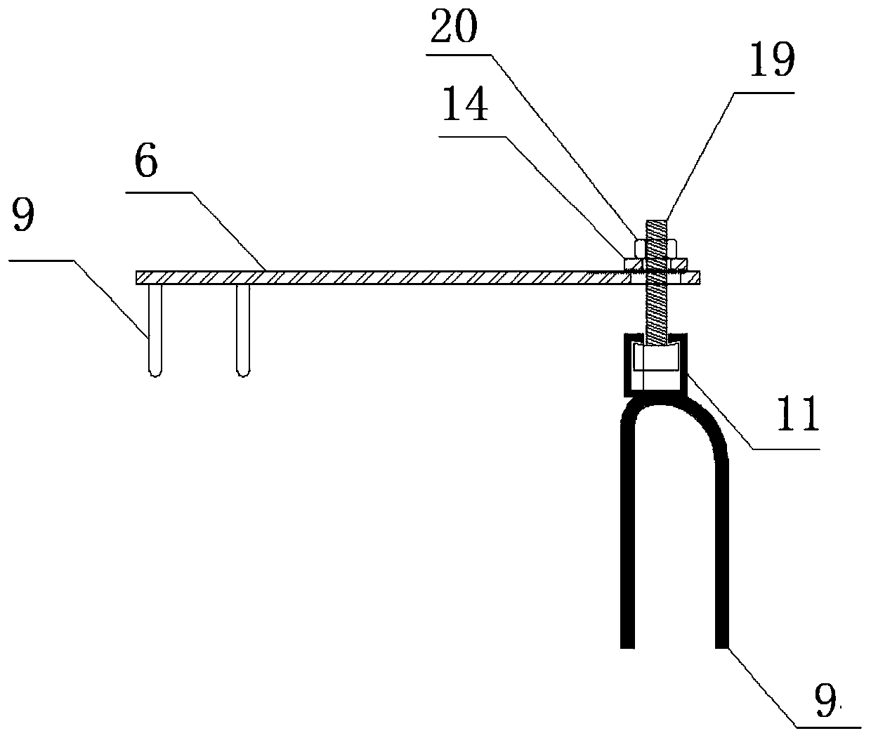
[0069] See attached Figure 7As shown, the embedded part 7 of the upper connection assembly in this embodiment includes the first sleeve 11 and the anchoring leg 9 embedded in the concrete of the side wall 102 of the bay window. In this embodiment, the first sleeve 11 is a hollow sleeve with openings at both ends and internal threads. The fixing part 8 includes a screw, a nut 20 and a washer 14 , the bottom of the screw is inserted into the top of the first hollow sleeve 11 and threaded, and the top of the screw is connected with the connecting part 6 throug...

Embodiment 3

[0072] The connection structure of the prefabricated integral bay window 1 in this embodiment differs from that in Embodiment 1 in that the specific structural form of the upper connection assembly 2 is different. See attached Figure 8 As shown, in this embodiment, the upper connection assembly 2 includes a connection part 6 , a pre-embedded part 7 and a fixing part 8 . Wherein, the connecting part 6 includes a second sliding groove 12 and a sliding rod 2525. The opening end of the second sliding groove 12 faces upward and is flush with the upper surface of the prefabricated part. The first end of the sliding rod 2525 is clamped on the second sliding In the groove 12 , the second end is connected with the fixing part 8 . The embedded part 7 is a positioning box 22 with an open top side, and the opening end surface of the positioning box 22 is flush with the lower surface of the groove 104 of the bay window. The fixed part 8 is an L-shaped plate 24, and the L-shaped plate 24...


PUM


Abstract

The invention provides a connection structure for a prefabricated integral bay window. The connection structure comprises a prefabricated integral bay window and a superposed beam and is characterizedin that the prefabricated integral bay window is integrally poured into a C-similar shape and comprises a top plate, a side wall and a bottom plate; the superposed beam comprises a prefabricated partand a cast-in-place part; the bottom surface of the bottom plate and the bottom surface of the prefabricated part are positioned on the same horizontal plane; the indoor side of the side wall is fixedly connected with the cast-in-place part through an upper connecting component; and the bottom plate is fixedly connected with the prefabricated part through a lower connecting component. When the connection structure for the prefabricated integral bay window in the scheme is produced and manufactured, no reinforcing steel bars extend out of the edge part of the prefabricated integral bay window,a production module is simple, demoulding efficiency is high, and a mould turnover frequency is improved. In a transportation stage, a loading rate can be improved; wet operations in an assembling field are few, form erection is avoided, field construction efficiency is improved, and construction cost is lowered; an error-tolerant rate of field assembling is high, the position of the prefabricated integral bay window can be regulated in field through ways, including gaskets, bolts, mortar, bed mortar and the like, and the connection structure disclosed by the invention is convenient for fieldinstallation and regulation.

Description

technical field [0001] The invention belongs to the technical field of prefabricated buildings, and in particular relates to a connection structure of a prefabricated integral bay window and an assembly method thereof. Background technique [0002] The prefabricated building is assembled from prefabricated components (PC parts), and the nodes between the PC parts are connected by connectors or cast-in-place concrete. Reasonable node design is the focus of ensuring the assembly quality of prefabricated buildings. The node design between PC parts must not only ensure the structural safety and normal use of functions, but also need to consider the difficulty and cost of prefabricated component manufacturing, transportation and on-site assembly. Assembled prefabricated integral bay windows can be divided into three-sided windows and single-sided windows according to the window opening direction. Among them, the bay windows with three-sided windows have better lighting and vision...

Claims


Application Information

Patent Timeline
Patent Type & Authority Applications(China)
IPC IPC(8): E04B1/04E04B1/38E04B1/41
CPCE04B1/04E04B1/043E04B1/38E04B1/41E04B1/4107
Inventor 俞大有李雪晨姚小旺
Owner CHINA MINGSHENG DRAWIN TECH INVESTMENT CO LTD
Why Eureka
Try Eureka