An AC plasma-oxygen-enriched ignition burner

A kind of ignition burner and burner technology, applied in the direction of burner, gas fuel burner, combustion type, etc., can solve the problem of poor adaptability of coal types, etc., and achieve the effect of prolonging the residence time

Active Publication Date: 2020-11-06
SHANXI UNIV
View PDF6 Cites 0 Cited by
  • Summary
  • Abstract
  • Description
  • Claims
  • Application Information

AI Technical Summary

Problems solved by technology

[0003] The purpose of the invention is to solve the problem of poor adaptability of coal types in AC plasma ignition technology
Provide an AC plasma-oxygen-enriched ignition burner

Method used


Image

  • An AC plasma-oxygen-enriched ignition burner
  • An AC plasma-oxygen-enriched ignition burner
  • An AC plasma-oxygen-enriched ignition burner

Examples


Embodiment 1

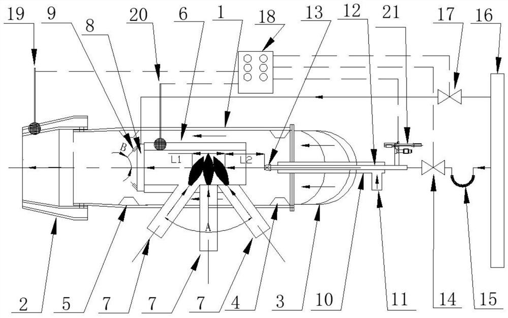
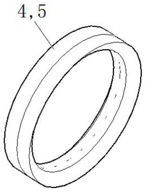
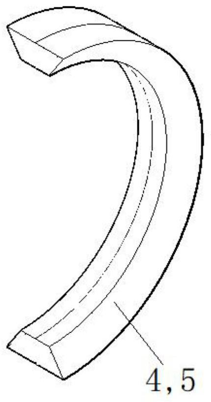
[0027] Such as Figure 1-5 As shown, an AC plasma-oxygen-enriched ignition burner in this embodiment includes a burner body 1, a nozzle 2 is provided at the left end of the burner body 1, and a nozzle 2 passes through the right end of the burner body 1. The flange is fixedly connected with a pulverized coal elbow 3, and a center cylinder 6 is provided inside the burner body 1 at the central axis of the burner body 1, and a center cylinder 6 is provided on the inner wall of the right end and the left end of the burner body 1 respectively. Level concentration ring 4 and secondary concentration ring 5, and make secondary concentration ring 5 be positioned at the exit of central tube 6, be provided with three alternating current plasma generators 7 on the outer wall of central tube 6, described alternating current plasma generator 7 on both sides The included angle of the axis of the generator 7 is 50°, so that the plasma arcs of the three AC plasma generators 7 converge at the ce...

Embodiment 2

[0030] Such as Figure 1-4 As shown, an AC plasma-oxygen-enriched ignition burner in this embodiment includes a burner body 1, a nozzle 2 is provided at the left end of the burner body 1, and a nozzle 2 passes through the right end of the burner body 1. The flange is fixedly connected with a pulverized coal elbow 3, and a center cylinder 6 is provided inside the burner body 1 at the central axis of the burner body 1, and a center cylinder 6 is provided on the inner wall of the right end and the left end of the burner body 1 respectively. Level concentration ring 4 and secondary concentration ring 5, and make secondary concentration ring 5 be positioned at the exit of central tube 6, be provided with three alternating current plasma generators 7 on the outer wall of central tube 6, described alternating current plasma generator 7 on both sides The included angle of the axis of the generator 7 is 80°, so that the plasma arcs of the three AC plasma generators 7 converge at the ce...

Embodiment 3

[0033] Such as Figure 1-4 As shown, an AC plasma-oxygen-enriched ignition burner in this embodiment includes a burner body 1, a nozzle 2 is provided at the left end of the burner body 1, and a nozzle 2 passes through the right end of the burner body 1. The flange is fixedly connected with a pulverized coal elbow 3, and a center cylinder 6 is provided inside the burner body 1 at the central axis of the burner body 1, and a center cylinder 6 is provided on the inner wall of the right end and the left end of the burner body 1 respectively. Level concentration ring 4 and secondary concentration ring 5, and make secondary concentration ring 5 be positioned at the exit of central tube 6, be provided with three alternating current plasma generators 7 on the outer wall of central tube 6, described alternating current plasma generator 7 on both sides The included angle of the axis of the generator 7 is 60°, so that the plasma arcs of the three AC plasma generators 7 converge at the ce...


PUM


Abstract

The invention belongs to the field of coal-fired boilers of thermal power plants, and particularly relates to an alternating current plasma-oxygen rich ignition combustor. The alternating current plasma-oxygen rich ignition combustor aims to solve the problem of poor coal type adaptability of an alternating current plasma ignition technology. The alternating current plasma-oxygen rich ignition combustor comprises a combustor body, a nozzle is arranged at the left end of the combustor body, a pulverized coal elbow is fixedly arranged at the right end of the combustor body, and a central cylinder is arranged at the position, located at the central axis of the combustor body, inside the combustor body. According to the alternating current plasma-oxygen rich ignition combustor, an included angle A between the axes of alternating current plasma generators on the two sides is greater than 50 degrees and less than 80 degrees, so that three plasma arcs are collected at the central axis of thecentral cylinder, so that the alternating current plasma-oxygen rich ignition combustor has the beneficial effects that the three plasma arcs are seamlessly connected at the axis of the central cylinder, then a continuous plasma arc fire core zone with the length L1 greater than or equal to 300 mm is formed, uninterrupted heating of the pulverized coal is achieved, and the stay duration of the pulverized coal at the fire core zone is prolonged, which are quite beneficial to ignition of carbon particles in coal, and therefore the alternating current plasma-oxygen rich ignition combustor is quite suitable for being used for igniting the inferior coal.

Description

technical field [0001] The invention belongs to the field of coal-fired boilers in thermal power plants, and in particular relates to an AC plasma-oxygen-enriched ignition burner. Background technique [0002] Large-scale thermal power coal-fired boilers need to consume a lot of fuel during cold start and low-load stable combustion. Therefore, a variety of fuel-saving technologies have emerged in recent years, and the micro-oil ignition technology and plasma ignition technology have been widely promoted and applied. Among them, plasma ignition technology has received extensive attention and research because it can achieve zero fuel consumption in boilers. However, its ignition power is small and it is mainly suitable for combustible coal types. For low-quality coal boilers, it is still necessary to use micro-oil ignition technology, or use Plasma ignition technology + large oil gun to support combustion. Plasma ignition technology is divided into DC plasma ignition technolo...

Claims


Application Information

Patent Timeline
Patent Type & Authority Patents(China)
IPC IPC(8): F23D14/32F23D14/48F23D14/46
CPCF23D14/32F23D14/46F23D14/48Y02E20/34
Inventor 闫高程
Owner SHANXI UNIV
Why Eureka
Try Eureka