Efficient feed drying device

A drying device and feed technology, applied in drying, dryer, drying gas arrangement and other directions, can solve the problems of low drying efficiency, direct drying of feed, etc., achieve high-efficiency drying, improve unevenness, improve The effect of drying

Active Publication Date: 2020-02-07
沈阳美神农牧科技有限公司
View PDF21 Cites 8 Cited by
  • Summary
  • Abstract
  • Description
  • Claims
  • Application Information

AI Technical Summary

Problems solved by technology

[0003] In the prior art, the feed is usually laid flat on the drying blanket, and the hot air is directly blown to dry it. This setting prevents the feed laid on the bottom from ...

Method used


Image

  • Efficient feed drying device
  • Efficient feed drying device
  • Efficient feed drying device

Examples


Embodiment 1

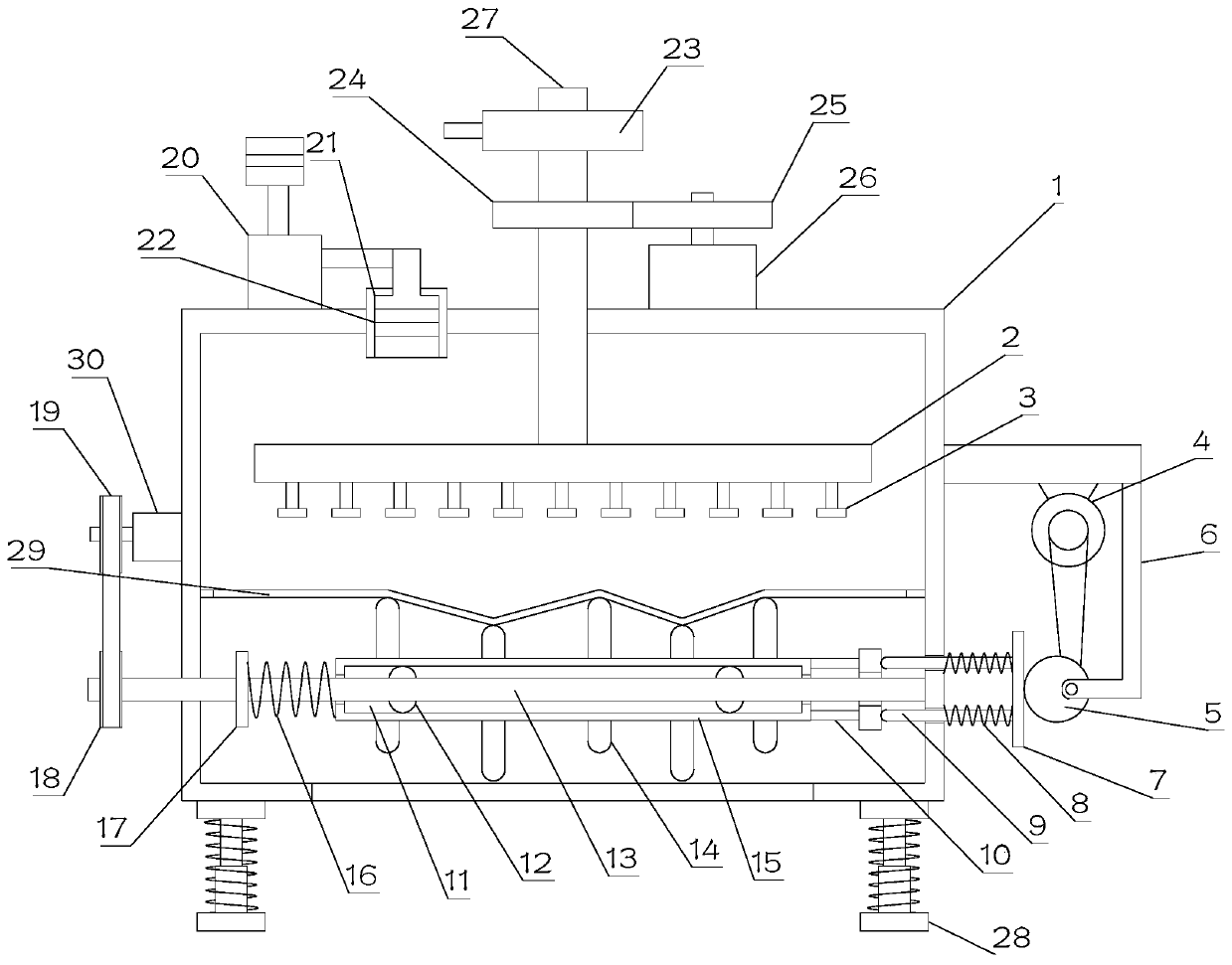
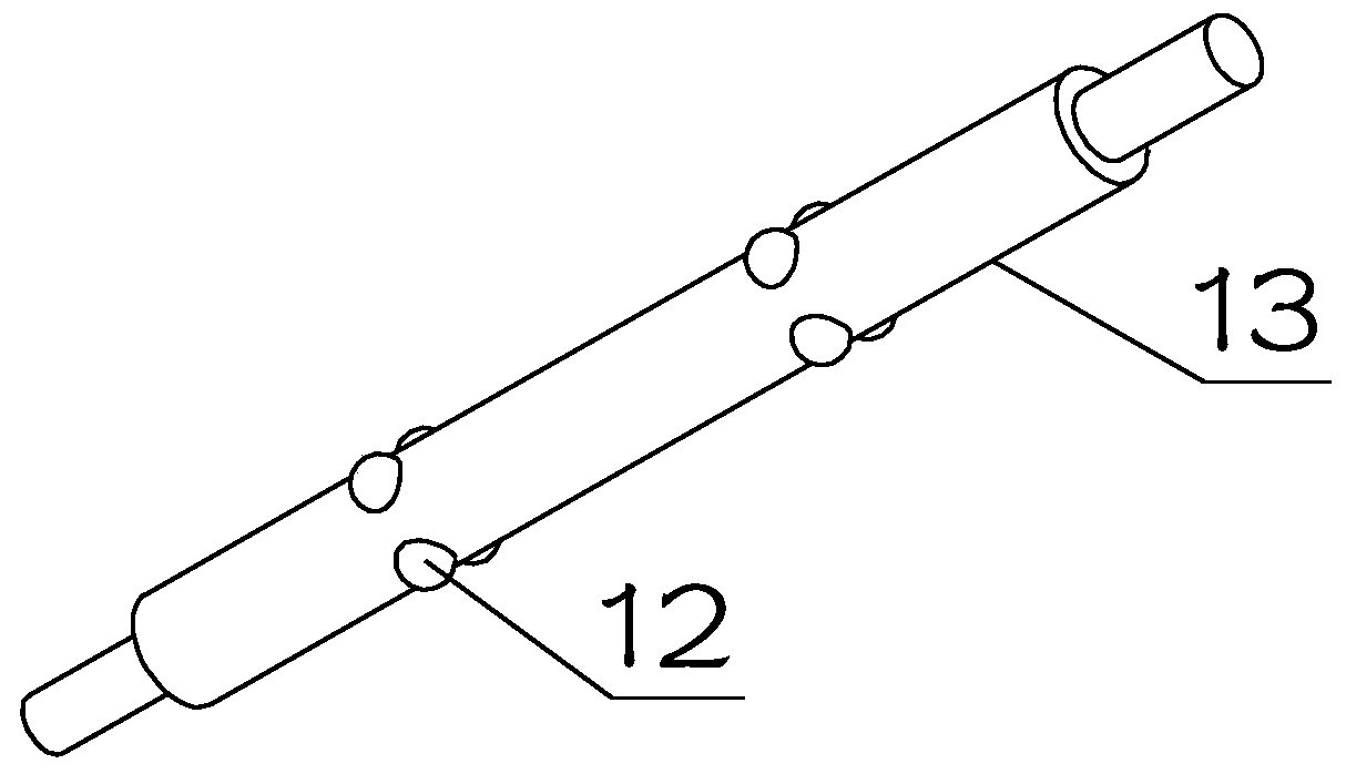
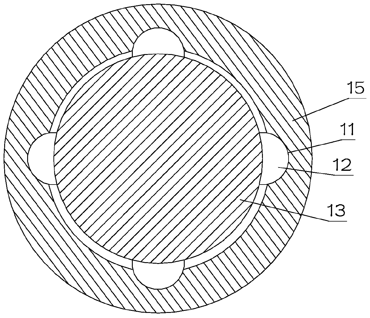
[0021] see Figure 1~3 , in Embodiment 1 of the present invention, a high-efficiency feed drying device includes a drying main body 1 with a drying chamber inside, an elastic drying film 29 is arranged inside the drying main body 1, and a sliding sleeve 15 is arranged outside There are multiple cams 14 with different installation angles. The upper ends of the cams 14 are in contact with the bottom of the elastic drying film 29, and are used to drive the elastic drying film 29 to reciprocate up and down; The rotating shaft 13 on 1 is used to drive the rotating shaft 13 to rotate. The outer side of the rotating shaft 13 is provided with a protrusion 12. The protrusion 12 slides left and right and is arranged on the sliding groove inside the sliding sleeve 15. The B sleeve on the rotating shaft 13 The two ends of the elastic member 16 are respectively fixed on one end of the sliding sleeve 15 and the supporting block 17, and the supporting block 17 is fixedly installed on the sli...

Embodiment 2

[0024] see Figure 1~3 The main difference between Embodiment 2 and Embodiment 1 is that a door is provided on the side of the drying body 1 for adding feed to the inside of the drying body 1 .

[0025] The rotating assembly includes an A belt pulley 18 sleeved on the rotating shaft 13, a B belt pulley 19 and a C motor 30 connected in transmission with the A belt pulley 18, the B belt pulley 19 is mounted on the output end of the C motor 30, and the C motor 30 is fixedly mounted on the oven. Dry main body 1. The C motor 30 is energized to provide power for the rotation of the rotating shaft 13 through the B pulley 19 and the A pulley 18 .

[0026] The reciprocating assembly includes a mating sleeve 10 fixedly installed on the other end of the sliding sleeve 15, the mating sleeve 10 is set on the rotating shaft 13, the pole 9 is in contact with the mating sleeve 10, and the pole 9 runs through the drying body 1 side The pole 9 is fixed on the end away from the mating sleeve 1...


PUM


Abstract

The invention discloses an efficient feed drying device, and relates to the technical field of feed processing. The drying device comprises a drying main body internally provided with a drying cavity,an elastic drying film is arranged in the drying main body, a plurality of cams with different mounting angles are arranged on the outer side of a sliding sleeve, and the upper ends of the cams abutagainst the bottom of the elastic drying film; the sliding sleeve is sleeved on a rotating shaft which is rotatably mounted on the drying main body, a protrusion is arranged on the outer side of the rotating shaft, the protrusion is arranged in a sliding groove of the sliding sleeve in a left-right sliding mode, the two ends of a B elastic part sleeved on the rotating shaft are fixed to one end ofthe sliding sleeve and a supporting block correspondingly, and the supporting block is fixedly installed on the sliding sleeve; a reciprocating assembly for driving the sliding sleeve to reciprocateleft and right is arranged at the other end of the sliding sleeve; a rotating assembly for driving the rotating shaft to rotate is arranged on the rotating shaft; and a rotating air injection assemblyis arranged above the elastic drying film. According to the efficient feed drying device, efficient drying of the feed and energy conservation are realized.

Description

technical field [0001] The invention relates to the technical field of feed processing, in particular to an efficient feed drying device. Background technique [0002] With the rapid development of the breeding industry, the demand for artificial feed is increasing, and people's requirements for the efficiency and quality of feed production are also getting higher and higher. [0003] In the prior art, the feed is usually laid flat on the drying blanket, and the hot air is directly blown to dry it. This setting prevents the feed laid on the bottom from being directly dried by the hot air, making the drying efficiency relatively low. Therefore, It is necessary to design a high-efficiency feed drying device to solve the above technical problems. Contents of the invention [0004] The purpose of the present invention is to provide a high-efficiency feed drying device to solve the problems raised in the above-mentioned background technology. [0005] To achieve the above obj...

Claims


Application Information

Patent Timeline
IPC IPC(8): F26B17/26F26B21/00F26B25/00F26B25/18
CPCF26B17/263F26B21/001F26B25/00F26B25/18
Inventor 张凌云
Owner 沈阳美神农牧科技有限公司
Why Eureka
Try Eureka