Remote multifunctional mutual inductor secondary circuit polarity tester

A secondary circuit and transformer technology, which is applied in the direction of electric winding test, dielectric strength test, instrument, etc., can solve the problems of protection device malfunction, blackout range, no published patent documents, and increased workload of the secondary end. Achieve the effect of improving operational flexibility, avoiding the risk of use, and long remote control distance

Inactive Publication Date: 2020-02-07
TIANJIN ELECTRIC POWER TRANSMISSION & TRANSFORMATION ENG CORP +2
View PDF8 Cites 1 Cited by
  • Summary
  • Abstract
  • Description
  • Claims
  • Application Information

AI Technical Summary

Problems solved by technology

Therefore, it is very important to verify the polarity direction of the secondary circuit of the transformer. If the polarity direction is wrong, it will cause the protection device to malfunction and cause the power outage to expand.
[0003] Now, in the process of relay protection debugging in all substations, the method of verifying the polarity direction of the transformer is relatively clumsy, and at least three people are required to cooperate with the walkie-talkie. a match
Moreover, the secondary circuit of the transformer does not have only one group but multiple groups, and the workload of the corresponding secondary end is greatly increased, and the work process will be relatively slow.
The traditional polarity direction verification method is time-consuming and labor-intensive, and it is also dangerous for personnel to touch dry batteries on the primary side all the time.
[0004] Through the search of published patent documents, no published patent documents similar to this patent application have been found

Method used


Image

  • Remote multifunctional mutual inductor secondary circuit polarity tester
  • Remote multifunctional mutual inductor secondary circuit polarity tester
  • Remote multifunctional mutual inductor secondary circuit polarity tester

Examples


Embodiment Construction

[0023] The present invention will be further described in detail below through the specific examples, the following examples are only descriptive, not restrictive, and cannot limit the protection scope of the present invention with this.

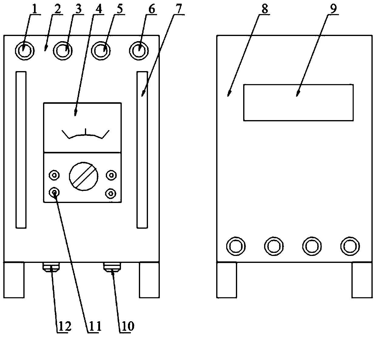
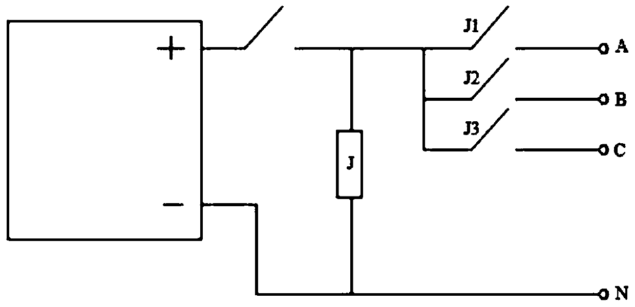
[0024] A remote multifunctional transformer secondary circuit polarity tester, characterized in that it includes a primary side control unit and a secondary side test unit, the primary side control unit includes a primary side housing 8 and is installed on the primary side A rechargeable lithium battery, a battery switch, a jog relay and three relay contact switches in the shell, the rechargeable lithium battery and the jog relay are connected in series, and the outer shell of the primary side is provided with terminals A and B Connection terminal 3, C connection terminal 5 and N connection terminal 6, the three relay contact switches are connected to the four connection terminals, and the four connection terminals are respectively connected ...


PUM


Abstract

The invention relates to a remote multifunctional mutual inductor secondary circuit polarity tester. The remote multifunctional mutual inductor secondary circuit polarity tester is characterized in that a rechargeable lithium battery is connected with an inching relay in series, four wiring terminals A, B, C and N are arranged outside a primary side shell, three relay contact switches communicatewith the four wiring terminals, and the four wiring terminals are respectively connected to the primary side loops of the mutual inductor; the four wiring terminals A, B, C and N are arranged outsidea secondary side shell, the four wiring terminals are respectively connected to the secondary side loops of the mutual inductor; a loop change-over switch and a function change-over switch are connected in series, and a polarity pointer meter and an insulation test meter / direct-current resistance tester are connected in parallel and jointly connected to the function change-over switch. The remotemultifunctional mutual inductor secondary circuit polarity tester is scientific and reasonable, is flexible and convenient to operate, can achieve the free conversion of six groups of loops and the testing of auxiliary DC resistance and loop insulation, reduces the manpower investment and operation risks, and improves the work efficiency.

Description

technical field [0001] The invention belongs to the technical field of transformer substation debugging in electric power systems, and relates to a transformer polarity testing device, in particular to a remote multifunctional transformer secondary circuit polarity testing instrument. Background technique [0002] In the modern power network, it is basically the form of power supply on both sides of the power network. Since there are power sources on both sides, in order to minimize the scope of power outages, circuit breakers and protection devices are installed on both sides of each line and can Determine the direction of current and voltage. Therefore, it is very important to verify the polarity direction of the secondary circuit of the transformer. If the polarity direction is wrong, it will cause the protection device to malfunction and cause the power outage to expand. [0003] Now, in the process of relay protection debugging in all substations, the method of verifyi...

Claims


Application Information

Patent Timeline
Patent Type & Authority Applications(China)
IPC IPC(8): G01R35/02G01R31/72G01R27/02G01R31/12
CPCG01R27/02G01R31/12G01R35/02
Inventor 李胜清张少江曹正李宝睿杨宝钰李鹏程嘉泰李禹郭志军
Owner TIANJIN ELECTRIC POWER TRANSMISSION & TRANSFORMATION ENG CORP
Why Eureka
Try Eureka