Display device and driving method thereof

A technology of a display device and a driving method, which is applied to static indicators, nonlinear optics, instruments, etc., can solve the problem of small visual angle of laser light, and achieve the effect of increasing the visual angle, improving user experience, and reducing specular reflection.

Active Publication Date: 2020-02-07
HUIZHOU CHINA STAR OPTOELECTRONICS TECHNOLOGY CO LTD
View PDF6 Cites 5 Cited by
  • Summary
  • Abstract
  • Description
  • Claims
  • Application Information

AI Technical Summary

Problems solved by technology

[0005] This application provides a display device and its driving method to solve the t

Method used


Image

  • Display device and driving method thereof
  • Display device and driving method thereof
  • Display device and driving method thereof

Examples


Embodiment 1

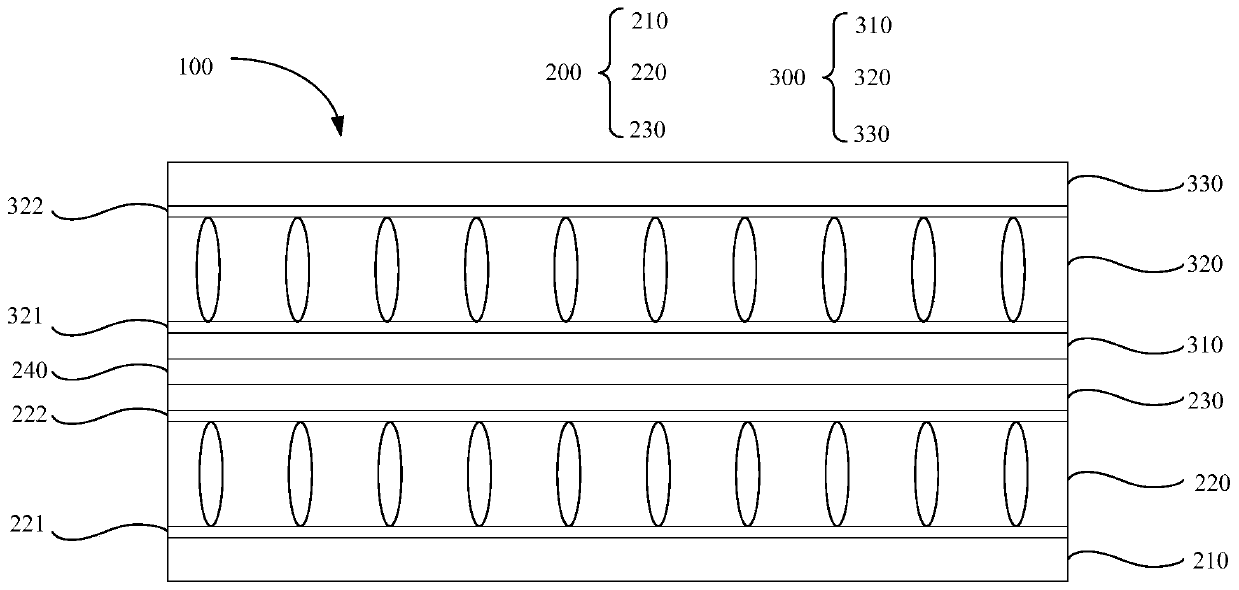
[0047] see figure 1 , the display device 100 includes:

[0048] The first liquid crystal cell 200 includes a first array substrate 210, a color filter layer 230 disposed opposite to the first array substrate 210, and a first color filter layer located between the first array substrate 210 and the color filter layer 230. Liquid crystal layer 220 .

[0049] The second liquid crystal cell 300 disposed opposite to the first liquid crystal cell 200 includes a drive circuit board 310 disposed close to the first liquid crystal cell 200, a cover plate 330 disposed away from the first liquid crystal cell 200, and a The second liquid crystal layer 320 between the driving circuit 310 and the cover plate 330 .

[0050] Wherein, the types of the first liquid crystal layer 220 and the second liquid crystal layer 320 are different.

[0051] In this embodiment, the material of the first liquid crystal layer 220 includes nematic liquid crystal. The material of the second liquid crystal lay...

Embodiment 2

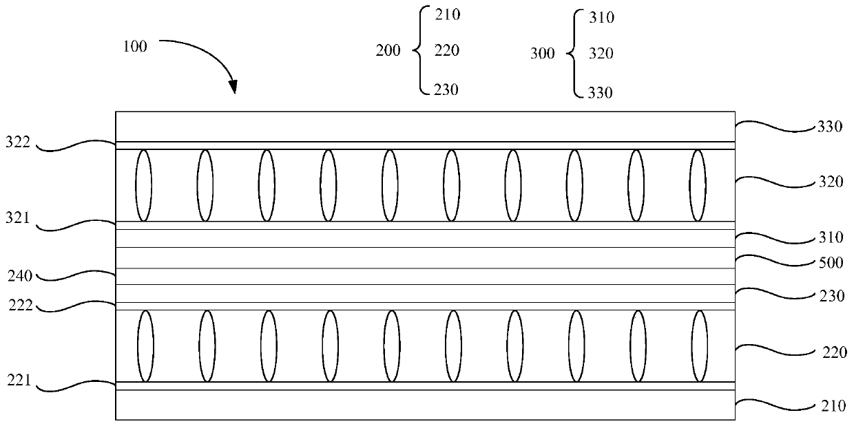
[0064] see image 3 , this embodiment is the same or similar to Embodiment 1, the difference is:

[0065] The display device 100 further includes a translucent semi-diffuse reflection layer 500 located between the first liquid crystal cell 200 and the second liquid crystal cell 300 .

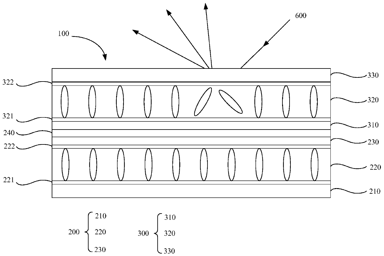
[0066] In this embodiment, the semi-diffuse reflective translucent layer 500 transmits incident light near the first liquid crystal cell 200 and diffusely reflects incident light far away from the first liquid crystal cell 200 . When the laser light does not increase the haze of the second liquid crystal cell 300, the laser light passes through the second liquid crystal cell 300, and the semi-diffuse reflection and translucent layer 500 can better diffusely reflect the laser light and emit the The display device 100 provides users with a better viewing angle, for details, please refer to image 3 , Figure 7 .

[0067] In this embodiment, the semi-diffuse reflective translucent layer 500 is ...

Embodiment 3

[0082] S10 . Scan the target display device 100 to acquire a first light intensity value of the first light source 600 .


PUM


Abstract

The invention discloses a display device and a driving method thereof. The display device comprises a first liquid crystal box and a second liquid crystal box, wherein the first liquid crystal box comprises a first liquid crystal layer, the second liquid crystal box is arranged in a way of being opposite to the first liquid crystal box and comprises a second liquid crystal layer, and the first liquid crystal layer is different from the second liquid crystal layer in type. According to the display device provided by the invention, the second liquid crystal box is arranged on the first liquid crystal box, when a laser light with certain light intensity irradiates on the display device, the second liquid crystal layer corresponding to the irradiated area is in a turn-off disordered state, thelaser light passes through liquid crystal molecules of such area, generates diffuse reflection and is shot out of the display device, thus, specular reflection of the laser light on the display device is weakened, a visible angle of the laser light is increased, and user experience is improved.

Description

technical field [0001] The present application relates to the display field, and in particular to a display device and a driving method thereof. Background technique [0002] Liquid crystal display (Liquid Crystal Display, LCD) is currently the most widely used display product in the market. Its production process technology is very mature, the product yield rate is high, the production cost is relatively low, and the market acceptance is high. [0003] The reflectivity of the surface of the liquid crystal display is high, so when the laser light emitted by the laser pointer is irradiated on the surface of the liquid crystal display, a mirror reflection will occur on the surface of the liquid crystal display, which reduces the visual angle of the laser in all directions and reduces the user experience. [0004] Therefore, there is an urgent need for a display device and a driving method thereof to solve the above technical problems. Contents of the invention [0005] The ...

Claims


Application Information

Patent Timeline
IPC IPC(8): G02F1/1347G02F1/1335G02F1/133
CPCG02F1/13306G02F1/133555G02F1/1347G02F1/133557
Inventor 黄东晨苏赞加
Owner HUIZHOU CHINA STAR OPTOELECTRONICS TECHNOLOGY CO LTD
Why Eureka
Try Eureka