Optical structure of LCD projector, projector and P light and S light conversion method
An optical structure and projector technology, applied in optics, instruments, projection devices, etc., can solve problems such as low light efficiency, low uniformity, and light clutter
- Summary
- Abstract
- Description
- Claims
- Application Information
AI Technical Summary
Problems solved by technology
Method used
Image

Examples
Embodiment
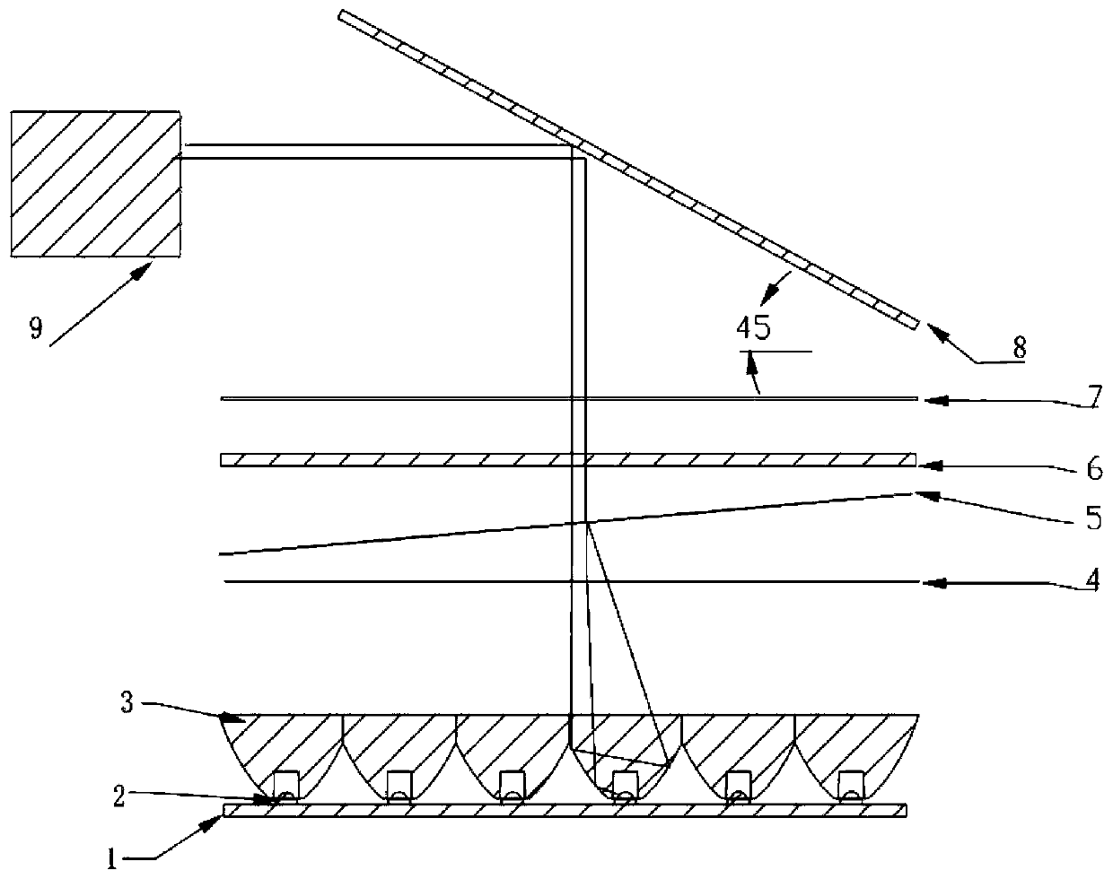
[0033] like figure 1 Shown: the technical problem to be solved in the present invention is to provide a kind of novel LCD projector optical structure, this structure is by LED array 1, with one-to-one corresponding primary lens 2 array and secondary lens 3 array, 1 / 4 wave plate 4. Reflective polarizer 5, liquid crystal screen 6, Fresnel lens 7, mirror 8 and lens 9 are composed, and the above components are arranged in sequence. Among them, the primary lens adopts a convex lens, and the secondary lens adopts a lamp cup type collimating and uniform light lens. The included angle between its Fresnel lens 7 and the mirror 8 is 45°. The secondary lens 3 array, the 1 / 4 wave plate 4, the liquid crystal screen 6, and the Fresnel lens 7 are parallel, and the lens 9 and the liquid crystal screen 6 are vertical.
[0034] Reflective polarizer 5 described in the present embodiment is not parallel to liquid crystal screen 6 and 1 / 4 wave plate 4, but has a small angle, as figure 1 shown...
PUM
| Property | Measurement | Unit |
|---|---|---|
| Angle of incidence | aaaaa | aaaaa |
Abstract
Description
Claims
Application Information
 - R&D
- Intellectual Property
- Life Sciences
- Materials
- Tech Scout
- Unparalleled Data Quality
- Higher Quality Content
- 60% Fewer Hallucinations
Browse by: Latest US Patents, China's latest patents, Technical Efficacy Thesaurus, Application Domain, Technology Topic, Popular Technical Reports.
© 2025 PatSnap. All rights reserved.Legal|Privacy policy|Modern Slavery Act Transparency Statement|Sitemap|About US| Contact US: help@patsnap.com