Eureka AIR delivers breakthrough ideas for toughest innovation challenges, trusted by R&D personnel around the world.

Light plasma tube pressure sealing system and pressure sealing method

A plasma tube and tube clamping technology, which is applied in the direction of electric tube/light off, etc., can solve the problems of difficult to guarantee product consistency and slow production efficiency, and achieve the effect of improving production efficiency, improving work efficiency and ensuring consistency.

Pending Publication Date: 2020-02-07
惠州市百欧森环保新材料有限公司
View PDF0 Cites 3 Cited by
  • Summary
  • Abstract
  • Description
  • Claims
  • Application Information

AI Technical Summary

Problems solved by technology

[0004] The first purpose of the present invention is to provide a light plasma tube sealing system, which aims to solve the technical problems of slow production efficiency and difficulty in ensuring product consistency

Method used


Image

  • Light plasma tube pressure sealing system and pressure sealing method
  • Light plasma tube pressure sealing system and pressure sealing method
  • Light plasma tube pressure sealing system and pressure sealing method

Examples


Embodiment 1

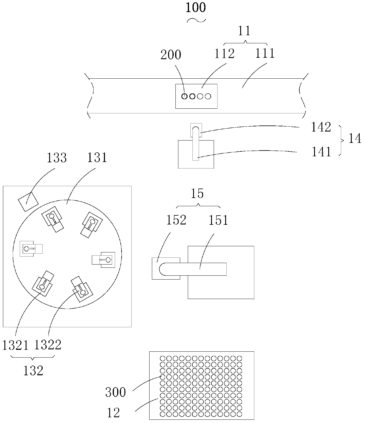
[0045] Such as Figure 1-4 As shown, the optical plasma tube sealing system 100 provided by the embodiment of the present invention is used to seal the electrode 300 at the end of the glass tube 200, including the glass tube transmission mechanism 11, the electrode placement frame 12, the sealing device, the first clamping device 14 and a second clamping device 15, wherein,

[0046] The glass tube delivery mechanism 11 is used to deliver the glass tube 200 , and includes a clamping tool 111 and a conveyor belt 112 for delivering the clamping tool 111 . The glass tube 200 is clamped and fixed on the tube clamping tool 111 . The clamping tool 111 not only has a place for placing the glass tube 200, but also has a place for placing semi-finished products.

[0047] The electrode placement rack 12 is arranged on one side of the glass tube conveying mechanism 11 for placing the electrodes 300 to be installed, and the electrodes 300 are placed on the electrode placement rack 12 in r...

Embodiment 2

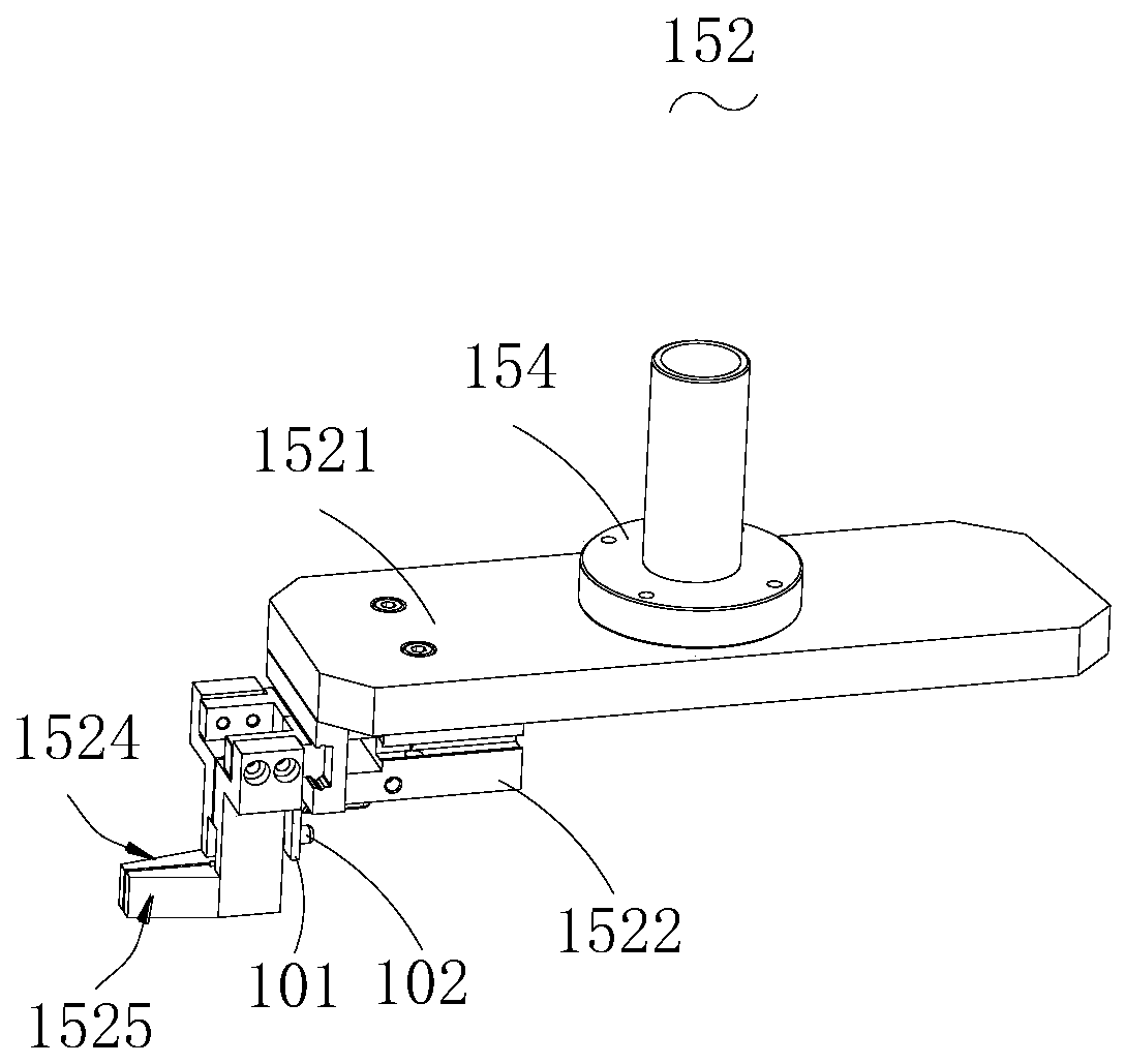
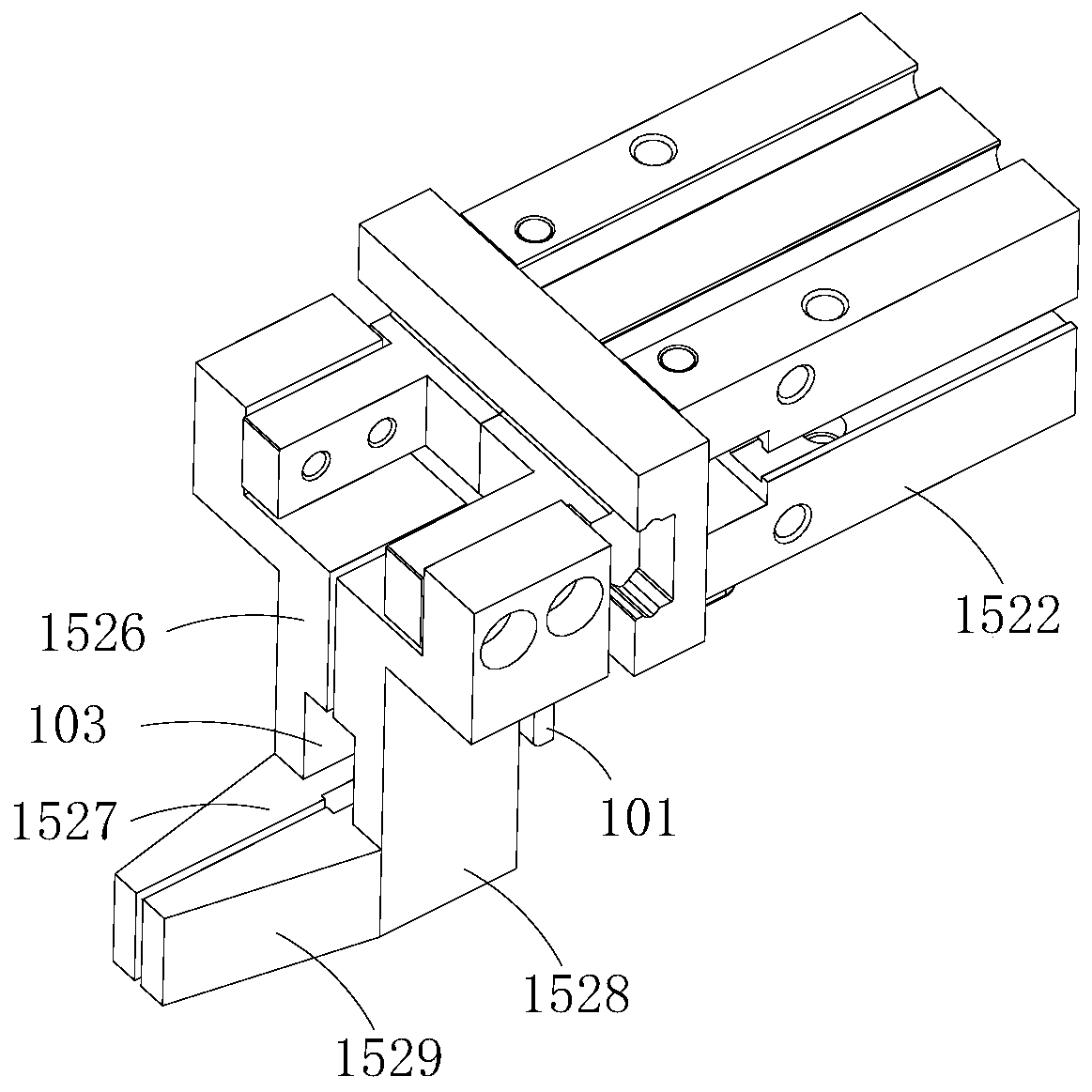
[0069] Such as Figure 3-Figure 7 As shown, the optical plasma tube sealing system 100 provided by the embodiment of the present invention is used to seal the electrode 300 at the end of the glass tube 200, including the glass tube transmission mechanism 11, the electrode placement frame 12, the sealing device, the first clamping device 14 and a second clamping device 15, wherein,

[0070] The glass tube delivery mechanism 11 is used to deliver the glass tube 200 , and includes a clamping tool 111 and a conveyor belt 112 for delivering the clamping tool 111 . The glass tube 200 is clamped and fixed on the tube clamping tool 111 . The clamping tool 111 not only has a place for placing the glass tube 200, but also has a place for placing semi-finished products.

[0071] The electrode placement rack 12 is arranged on one side of the glass tube conveying mechanism 11 for placing the electrodes 300 to be installed, and the electrodes 300 are placed on the electrode placement rack ...


PUM


Abstract

The invention discloses a light plasma tube pressure sealing system and a pressure sealing method. The light plasma tube pressure sealing system is used for pressure sealing of an electrode at the endof a glass tube. The light plasma tube pressure sealing system includes a glass tube transfer mechanism, an electrode placing rack, a pressure sealing device, a first clamping device and a second clamping device; the pressure sealing device includes a rotating frame, a first driving mechanism, workbenches for positioning the glass tube and the electrode, and a pressure sealing mechanism for pressure sealing; at least two workbenches are provided, and the two workbenches are spaced from each other in the rotation direction of the rotating frame; the first clamping device includes a first robotarm and a first glass tube clamp installed on the end of the first robot arm; and the second clamping device includes a second robot arm and an electrode clamp installed at the end of the second robot arm. The light plasma tube pressure sealing system can realize automatic pressure sealing operation, can ensure the consistency of the products, and can separate the positioning process from the pressure sealing process; therefore, the pressure sealing mechanism can work continuously, and the work efficiency is further improved.

Description

technical field [0001] The invention relates to the technical field of photoplasma tube production equipment, in particular to a photoplasma tube pressure sealing system and a pressure sealing method. Background technique [0002] The production of optical plasma tubes includes processes such as compression sealing and exhausting. At present, the equipment used to realize the compression sealing process is a kind of artificial mechanical production equipment. Each equipment needs a person to assist in the production to complete the production action. The quality of the product The level of quality depends on the operating level and mood of the personnel using the equipment, and the following problems are prone to occur: first, the consistency of the product cannot be guaranteed; second, the daily output of an operator who has worked for 10 years is 600-650 pieces; Third, the efficiency of the equipment is low, the energy consumption is quite high, and the waste of resources ...

Claims


Application Information

Patent Timeline
IPC IPC(8): H01J9/40
CPCH01J9/40
Inventor 罗威赵鹏植才杰陈建
Owner 惠州市百欧森环保新材料有限公司
Why Eureka
Eureka Blog
Learn More