
A machining device for box-shaped electronic components

An electronic component and mechanical processing technology, which is applied in the field of mechanical processing devices for box-shaped electronic components, can solve the problems of increased difficulty, small size, and difficulty in taking out electronic components, so as to improve stability, improve buffering effect, and improve stamping. The effect of stability

Active Publication Date: 2021-04-20
XUZHOU FLY DREAM ELECTRONICS & TECH
View PDF5 Cites 0 Cited by
  • Summary
  • Abstract
  • Description
  • Claims
  • Application Information

AI Technical Summary

Problems solved by technology

[0003] The existing processing method of this box-shaped electronic component is to place the sheet above the groove of the die, and then install the punch on the punch of the stamping equipment. After starting the stamping equipment, the punch presses the sheet into the cavity. In-mold, so that box-shaped electronic components are obtained in the groove of the die. Due to the stamping process, the electronic components after stamping are easily squeezed and embedded in the groove, and it is not easy to take the electronic component out of the groove. At the same time, because the box-shaped electronic components are too small, it makes the demoulding operation more difficult.

Method used


Image

  • A machining device for box-shaped electronic components
  • A machining device for box-shaped electronic components
  • A machining device for box-shaped electronic components

Examples


Embodiment 1

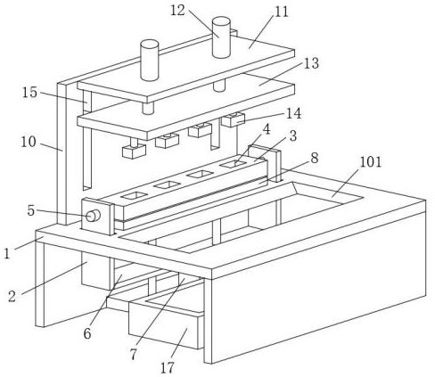
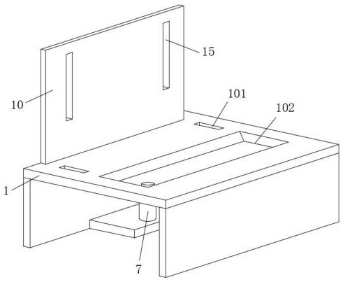
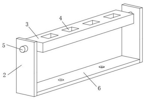
[0040] see Figure 1-3 , a machining device for box-shaped electronic components, comprising an operating table 1, lifting plates 2 slidably connected to both sides of the upper end of the operating table 1, and a workpiece placement plate rotatably installed between the two lifting plates 2 near the upper ends of the opposite side walls 3. Both sides of the upper end of the console 1 are provided with hollow cavities 101 for the elevating plate 2 to penetrate through. The first electric telescopic cylinder 7 that drives the bottom plate 6 is fixedly installed, and the outer wall of the upper end of one of the lifting plates 2 is fixedly installed with a rotating motor 5 that drives the workpiece placing plate 3, and the upper ends of the workpiece placing plate 3 are equally spaced along the horizontal direction A plurality of workpiece stamping grooves 4 are provided, and the inner walls of the plurality of workpiece stamping grooves 4 are coated with nano-wear-resistant coa...


PUM


Abstract

The invention discloses a machining device for box-shaped electronic components, which belongs to the technical field of electronic processing. The workpiece placement plate between the two lifting plates near the upper end of the opposite side wall, the workpiece placement plate for placing thin sheet materials can move up and down in the vertical direction, and when it falls against the buffer plate at the bottom, it is easy to improve the buffer during stamping The effect is that after stamping, it moves upwards and tilts downwards, which is easy to demould the stamped workpiece. At the same time, the upper elastic magnetic attraction mechanism and the buffer plate magnetic attraction are set. When the workpiece placing plate rises, when the upward elastic stretching force is greater than During magnetic attraction, after the upper elastic magnetic attraction mechanism is separated from the buffer plate, the upper elastic magnetic attraction mechanism gives an upward knocking impact force to the bottom of the workpiece placement plate, which is easier to demould the workpiece in the workpiece stamping groove.

Description

technical field [0001] The invention relates to the technical field of electronic processing, and more specifically, relates to a machining device for box-shaped electronic components. Background technique [0002] The USB interface of electronic equipment is often directly exposed and installed on the surface of the equipment body. The exposed USB interface is easy to be contaminated with a lot of dust, especially for some electronic equipment on construction sites or outdoors. If the USB interface of these devices has not been cleaned for a long time , Due to the accumulation of dust at the interface, the sensitivity of the equipment will be reduced or the equipment will be directly damaged. In the prior art, a box-shaped electronic component is designed for this phenomenon, which is mainly used to be inserted into the USB interface of the electronic device, so as to prevent external dust from entering these devices and play a role in blocking dust. [0003] The existing ...

Claims


Application Information

Patent Timeline
Patent Type & Authority Patents(China)
IPC IPC(8): B21D51/52B21D37/12B21D43/00B21D43/02B21D45/10
CPCB21D37/12B21D43/003B21D43/02B21D45/10B21D51/52
Inventor 陈迎程义阚森
Owner XUZHOU FLY DREAM ELECTRONICS & TECH
Learn More