
Boring clamp and operation method thereof

A boring jig and jig technology, applied in the direction of clamping, manufacturing tools, supports, etc., can solve the problems of difficulty in aligning the workpiece, great influence on hole accuracy, and affecting machining accuracy, etc., and achieve high efficiency in clamping and alignment , Improve the clamping efficiency and ensure the effect of machining accuracy

Active Publication Date: 2020-02-11
AECC AVIATION POWER CO LTD
View PDF6 Cites 6 Cited by
  • Summary
  • Abstract
  • Description
  • Claims
  • Application Information

AI Technical Summary

Problems solved by technology

[0002] During the processing of the compressor casing, since the shape of the workpiece to be processed is semicircular, the alignment process of the workpiece is extremely difficult; in the prior art, the alignment method of the workpiece during the boring process of the longitudinal joint surface is mostly manual alignment. Alignment efficiency is low
In addition, the compressor case has a thin-walled structure, and its material Ti40 is a difficult-to-machine material. The vibration of the workpiece during the processing has a great influence on the accuracy of the hole; the current workpiece clamping is mostly the clamping method of the pressure plate. It will cause the workpiece to vibrate due to uneven force, which will affect the machining accuracy

Method used


Image

  • Boring clamp and operation method thereof
  • Boring clamp and operation method thereof
  • Boring clamp and operation method thereof

Examples


Embodiment Construction

[0059] In order to make the purpose, technical effects and technical solutions of the embodiments of the present invention more clear, the technical solutions in the embodiments of the present invention are clearly and completely described below in conjunction with the accompanying drawings in the embodiments of the present invention; obviously, the described embodiments It is a part of the embodiment of the present invention. Based on the disclosed embodiments of the present invention, other embodiments obtained by persons of ordinary skill in the art without making creative efforts shall all fall within the protection scope of the present invention.

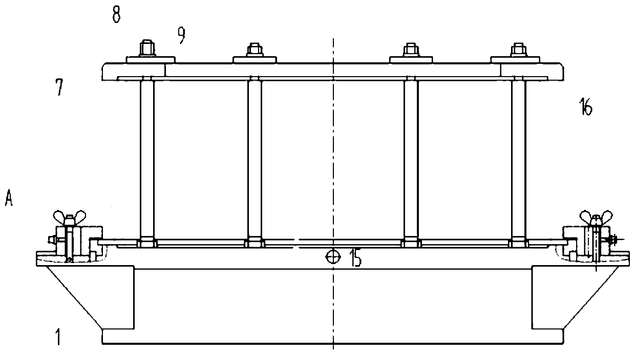
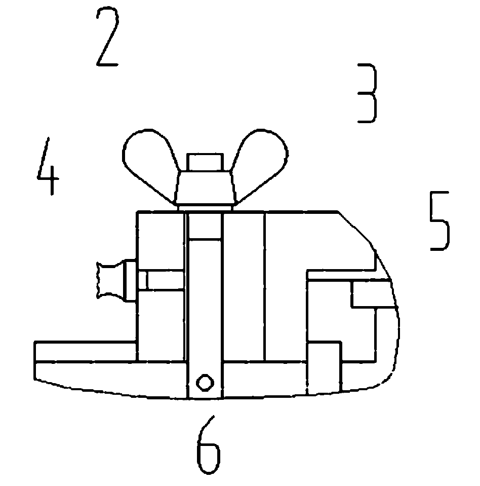
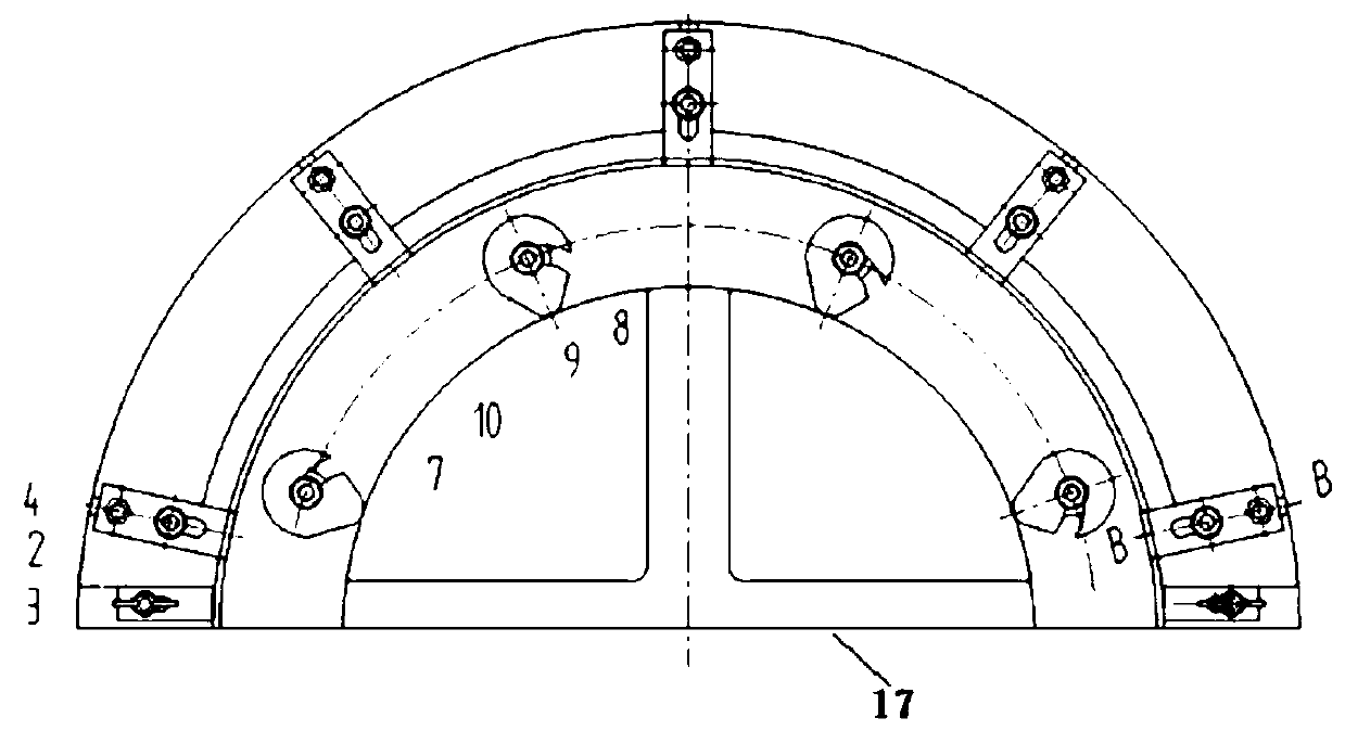
[0060] see Figure 1 to Figure 12 , a boring jig according to an embodiment of the present invention is a boring jig used for processing the casing of a compressor, which can be clamped quickly through a U-shaped groove structure to realize fast and accurate positioning of the workpiece, reduce alignment and clamping time, and ...


PUM


Abstract

The invention discloses a boring clamp and an operation method thereof. The boring clamp includes a clamp body and a pressing ring; the clamp body is provided with a base, and a semi-cylinder structure is fixed and supported on the base; the semi-circular cylinder structure includes an upper end surface, an arc surface and a side end surface; the upper end surface is a workpiece mounting surface;the side end surface is a straightening datum surface; a datum hole is formed in the clamp body; a semi-circular clamp rabbet is machined in the upper end surface; a positioning block on the left sideand a positioning block on the right side are slidably mounted on the upper end surface; the positioning block on the left side and the positioning block on the right side are symmetrical about the center of the clamp rabbet; a plurality of pressing plates are slidably arranged on the upper end surface in the circumferential direction; and the pressing ring is in a semi-circular shape, is mountedon the clamp body through a connecting device and used for clamping the upper end of a workpiece on the clamp body. The boring clamp can realize the quick alignment of the workpiece, and the alignment efficiency is high; and the force of the workpiece is uniform, so that the machining precision is not affected.

Description

technical field [0001] The invention belongs to the technical field of mechanical manufacturing, relates to the technical field of engine part manufacturing auxiliary fixtures, and in particular relates to a boring fixture and an operating method thereof. Background technique [0002] During the processing of the compressor casing, since the shape of the workpiece to be processed is semicircular, the alignment process of the workpiece is extremely difficult; in the prior art, the alignment method of the workpiece during the boring process of the longitudinal joint surface is mostly manual alignment. The alignment efficiency is low. In addition, the compressor case has a thin-walled structure, and its material Ti40 is a difficult-to-machine material. The vibration of the workpiece during the processing has a great influence on the accuracy of the hole; the current workpiece clamping is mostly the clamping method of the pressure plate. It will cause the workpiece to vibrate d...

Claims


Application Information

Patent Timeline
Patent Type & Authority Applications(China)
IPC IPC(8): B23Q3/06B23B35/00
CPCB23B35/00B23Q3/06
Inventor 汤婷婷苟浩洲吴惠雯杨琼常广利王建勋陈园源曹宗林
Owner AECC AVIATION POWER CO LTD
Learn More