Sliding type building plastic template punching machine

A plastic formwork and sliding technology, which is applied in the field of punching machines, can solve the problems of damage to plastic building formwork and the bottom of the hole is large, etc., and achieve the effect of precise punching position and prevention of damage

Active Publication Date: 2020-02-11
滨州市恒顺塑板制造有限责任公司
View PDF6 Cites 3 Cited by
  • Summary
  • Abstract
  • Description
  • Claims
  • Application Information

AI Technical Summary

Problems solved by technology

[0003] At present, when the plastic building formwork is drilled, the plastic building formwork that needs to be drilled is placed under the drill bit, the position where the plastic building formwork needs to be drilled is placed under the drill bit, and then the plastic building formwork is drilled. In this way, when drilling holes, the bottom of the plastic building formwork will make the bottom of the hole larger due to the force of the drill bit, and even damage the plastic building formwork

Method used


Image

  • Sliding type building plastic template punching machine
  • Sliding type building plastic template punching machine
  • Sliding type building plastic template punching machine

Examples


Embodiment 1

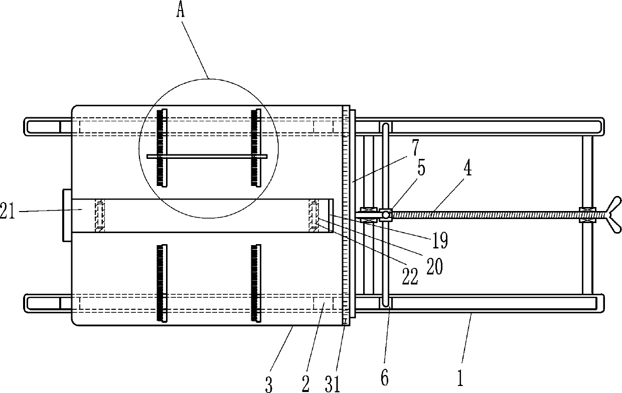
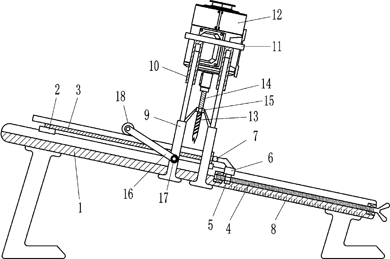
[0020] A sliding type construction plastic formwork puncher, such as figure 1 and 2 As shown, it includes a track 1, a sliding placement part, a limiting part and a punching part. There are two track 1s. There is a position-limiting component that is limited by rotation, and the middle part of the track 1 is provided with a punching component that is drilled by rotation.

[0021] like figure 1 and 2 As shown, the sliding part includes a first slider 2 and an L-shaped plate 3, and two first sliders 2 are slidably connected to the left and right parts of the track 1, and the tops of the first sliders 2 are fixed with L Shaped plate 3, the right side of the top of the L-shaped plate 3 is engraved with a first scale 31.

[0022] like figure 1 and 2 As shown, the limiting component includes a screw mandrel 4, a first nut 5, a second slider 6 and a limit rod 7, and a screw mandrel 4 is rotatably connected between the right part of the track 1, and a first screw mandrel 4 is sc...

Embodiment 2

[0029] like figure 1 As shown, on the basis of Embodiment 1, in order to punch holes more stably, it also includes a swing lever 16, a torsion spring 17 and a pressure roller 18, and the lower parts of the brackets 9 on the front and rear sides are connected to the swing lever 16 in a rotational manner. A torsion spring 17 is provided at the rotational connection of the swing rod 16 , and a pressure roller 18 is rotationally connected between the outer ends of the swing rod 16 .

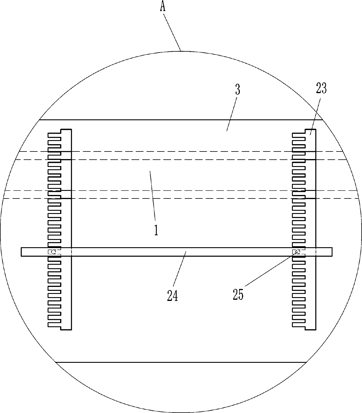
[0030] like figure 2 As shown, in order to prevent the building plastic formwork from being damaged, it also includes a concave backing plate 20, an inserting plate 21 and a block 22, and the left middle part of the L-shaped plate 3 has a groove 19, and the left and right parts in the groove 19 are all provided with There is a concave backing plate 20 on which a flashboard 21 is placed, and the left and right sides of the bottom of the flashboard 21 are provided with blocks 22 , and the snap blocks...


PUM


Abstract

The invention relates to a punching machine, in particular to a sliding type building plastic template punching machine, and aims at achieving the technical purpose of providing the sliding type building plastic template punching machine capable of preventing a building plastic template from being damaged and accurate in punching. The sliding type building plastic template punching machine comprises tracks, sliding containing components, limiting components, punching components and the like. The two tracks are arranged, the left portions of the tracks are provided with the sliding containing components, the sliding containing components drive the building plastic template to move in a sliding manner, the right portions of the tracks are provided with the limiting components for limiting ina rotation manner, and the middle portions of the tracks are provided with the punching components for drilling in a rotation manner. According to the sliding type building plastic template punchingmachine, through sliding of L-shaped plates, the position of the building plastic template can be better changed, the building plastic template can be more accurately punched, the limiting componentscan accurately control the punching position of the building plastic template in the left-right direction, and the building plastic template punching position is more accurate.

Description

technical field [0001] The invention relates to a punching machine, in particular to a sliding type building plastic formwork punching machine. Background technique [0002] Plastic building formwork has become the new favorite of the construction industry due to its environmental protection, energy saving, recycling, economical benefits, waterproof and corrosion resistance. , Optimizing the environment, low-carbon emission reduction plays a huge role, and it is a complete revolution in engineering formwork materials. When plastic building templates are used, holes need to be punched. [0003] At present, when the plastic building formwork is drilled, the plastic building formwork that needs to be drilled is placed under the drill bit, the position where the plastic building formwork needs to be drilled is placed under the drill bit, and then the plastic building formwork is drilled. When drilling holes in this way, the bottom of the plastic building formwork will be large...

Claims


Application Information

Patent Timeline
IPC IPC(8): B26F1/16B26D7/01B26D7/02B26D7/06B26D7/00
CPCB26D7/00B26D7/015B26D7/025B26D7/06B26F1/16
Inventor 周月婷
Owner 滨州市恒顺塑板制造有限责任公司
Why Eureka
Try Eureka