
Modular mold for prefabricated upright post pouring

A modular and mold technology, applied in molds, manufacturing tools, mold fixing devices, etc., can solve problems such as failure to realize column processing, and achieve the effect of fast fixing connection stability, reducing production costs, and saving processing materials.

Active Publication Date: 2020-02-11
绍兴市城投建筑工业化制造有限公司 +1
View PDF7 Cites 15 Cited by
  • Summary
  • Abstract
  • Description
  • Claims
  • Application Information

AI Technical Summary

Problems solved by technology

[0004] The above-mentioned patent introduces modular side forms in the processing of the formwork system, and splits the original one-piece side form structure into modular side form structures with different lengths along the length direction of the side forms. When it is necessary to change the height of the side forms , it is only necessary to increase or decrease the number of modular side molds on the basis of the original side molds. It is very convenient to change the height and size of the side molds. Modular modules with the same cross-sectional size can process multiple columns with different heights, which saves processing materials and reduces production costs; however, the above invention is only for processing columns with the same cross-sectional size and different heights. When the cross-sectional size of the column occurs When changing, it is still necessary to process modular side forms of the same size correspondingly, and it is not possible to process columns of different cross-sectional sizes and heights with a set of modular side forms

Method used


Image

  • Modular mold for prefabricated upright post pouring
  • Modular mold for prefabricated upright post pouring
  • Modular mold for prefabricated upright post pouring

Examples


Embodiment

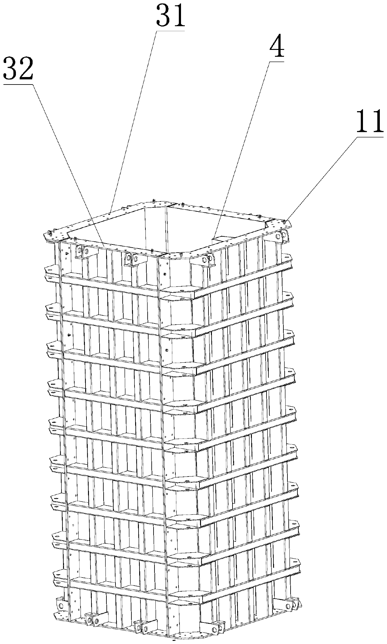
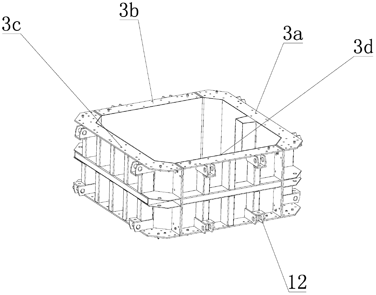
[0036] Such as Figure 1 to Figure 5 As shown, a modular mold for pouring prefabricated columns includes a bottom mold 1 and a side mold 2 detachably connected to the bottom mold. The side mold of the modular structure is formed by splicing side mold sections 3 with different lengths. The inner wall of the mold section is provided with a rain gutter 4 along its thickness direction. The side mold section includes a wide formwork 31 and a narrow formwork 32. The side mold section is formed by interlacing the wide formwork and the narrow formwork, and is connected to an end surface of the side formwork. The bottom mold of the bottom mold is provided with a positioning component 5 for positioning the reinforcement skeleton. After the side mold and the bottom mold are installed, a complete processing mold is formed. The middle part of the processing mold is provided with a grouting groove 6 along its length direction, and the reinforcement skeleton is located in the grouting groove....


PUM


Abstract

The invention discloses a modular mold for prefabricated upright post pouring. The modular mold aims to solve the technical problem that in the prior art, a mold for machining prefabricated upright posts needs to be customized according to the size of upright posts, and a number of molds is discarded after the upright posts are subjected to one-time grouting machining. The modular mold comprises abottom mold and a side mold detachably connected with the bottom mold, wherein the side mold of the modular structure is formed by splicing side mold sections with unequal lengths, the inner wall surfaces of the side mold sections are provided with rain grooves in the thickness direction of the side mold sections, the side mold sections comprise wide mold plates and narrow mold plates, the side mold sections are formed by staggered splicing of the wide mold plates and the narrow mold plates, a positioning assembly for positioning a reinforcement skeleton is arranged on the bottom mold connected with one end surface of the side mold, a complete machining mold is formed after the side mold and the bottom mold are installed, a grouting groove along the length direction of the machining moldis formed in the middle of the machining mold, and the reinforcement skeleton is located in the grouting groove and is tightly attached to the inner wall surface of the side mold. According to the modular mold for prefabricated upright post pouring, a group of modular side mold can be used for machining the upright posts with different sizes, so that the production cost is reduced.

Description

technical field [0001] The invention relates to the field of building construction, in particular to a modular mold for pouring prefabricated columns. Background technique [0002] With the promotion and popularization of bridge prefabricated assembly construction technology in urban bridge construction, the emergence of a large number of prefabricated columns and prefabricated cap beams has gradually standardized bridge construction. The existing column processing is usually to process the column mold that meets the size requirements in the factory after obtaining various data of the column, and then process the column through concrete mold pouring. When the height of the column required at the construction site is different, just It is necessary to process multiple molds with different heights. After the column is processed, the used mold may be discarded because its height is inconsistent with the column height requirements of the new construction site. At the same time, ...

Claims


Application Information

Patent Timeline
IPC IPC(8): B28B7/00
CPCB28B7/0002B28B7/0014B28B7/0029
Inventor 宁英杰何智钢潘森兵斯振兴黄祎涵
Owner 绍兴市城投建筑工业化制造有限公司
Learn More