
Transmission mechanism of sheet inserting machine

A technology of transmission mechanism and chip inserter, applied in mechanical conveyors, conveyors, packaging, etc., can solve the problems of low installation accuracy, seized bolts, easy oxidation, etc.

Pending Publication Date: 2020-02-11
晶海洋半导体材料(东海)有限公司
View PDF0 Cites 0 Cited by
  • Summary
  • Abstract
  • Description
  • Claims
  • Application Information

AI Technical Summary

Problems solved by technology

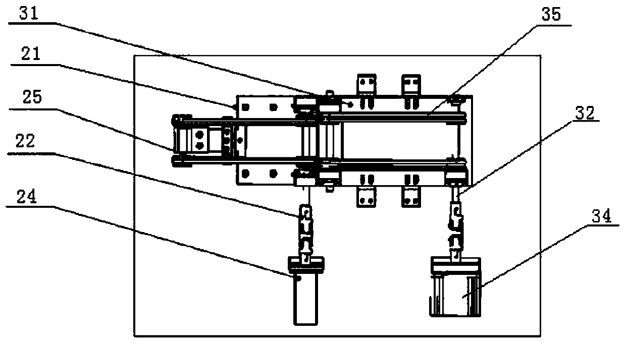
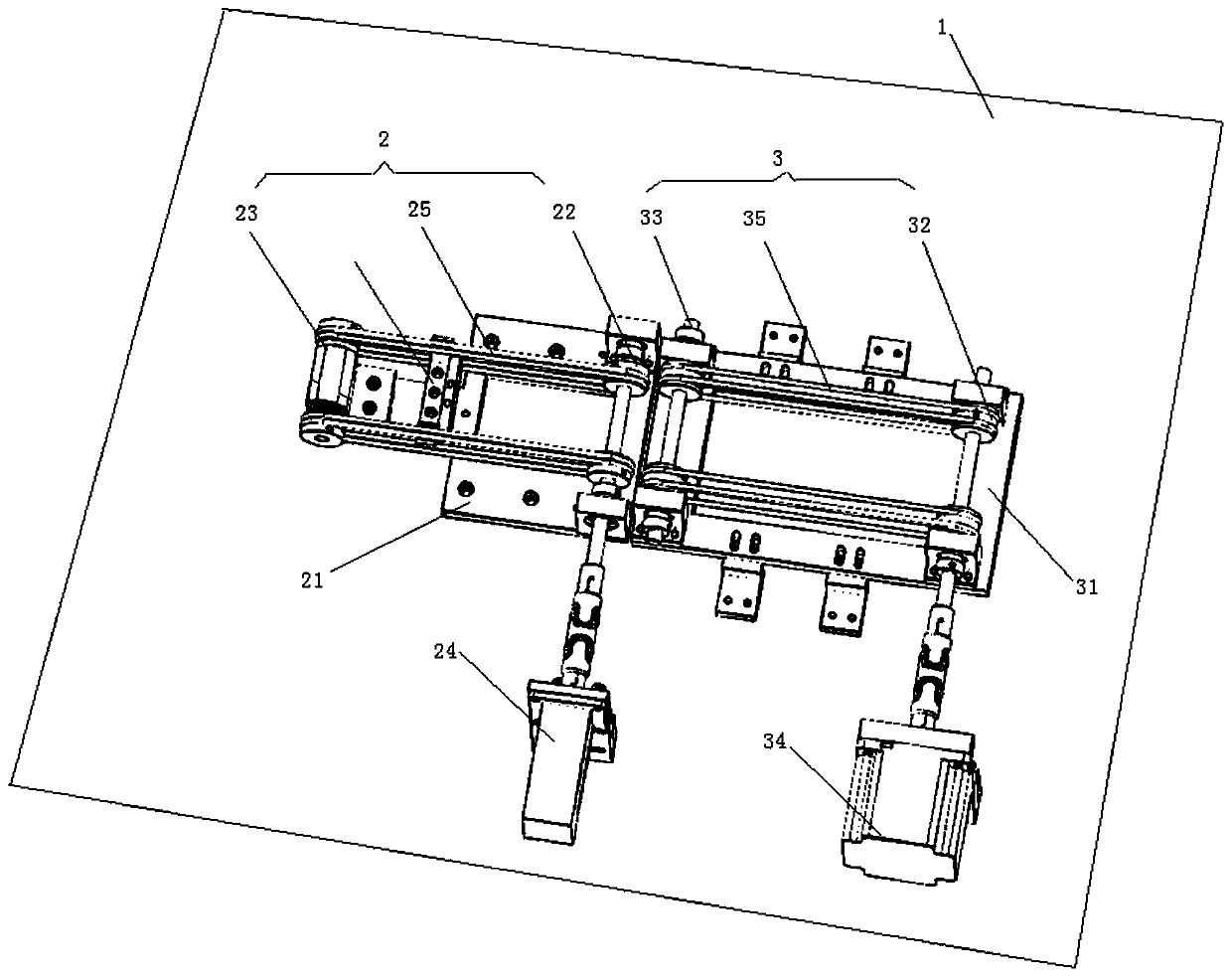
[0003] The transmission mechanism of the existing silicon wafer inserting machine mainly includes a whole base plate and a transmission shaft, a transmission belt, a transmission motor and a wafer stop distributed on the overall base plate. In order to sort out broken silicon wafers, three Section speed, corresponding to three sets of transmission shafts, transmission motors and transmission belts, they are intricately arranged on the whole bottom plate, making the structure of the entire transmission mechanism complex, although this can play a certain role in sorting, but due to the complex structure, Moreover, the output shaft is not running smoothly, and the belt is prone to jumping, which will cause the adjacent silicon wafers to collide and break during operation, reducing the yield rate; in addition, there are no positioning points for each component during installation, so , the installation accuracy is low. If disassembly and maintenance are carried out later, it will consume a lot of time to adjust the positioning; in addition, the wire holes on the aluminum base plate used to fix the components are easily oxidized when in contact with the cleaning liquid for a long time, and the bolts are seized, which greatly reduces the The service life of the product is shortened, and the cost of production and maintenance is increased. Moreover, once a certain transmission component fails, the intricate installation structure makes the overall disassembly and assembly troublesome, and the later installation and adjustment are also difficult.

Method used


Image

  • Transmission mechanism of sheet inserting machine
  • Transmission mechanism of sheet inserting machine
  • Transmission mechanism of sheet inserting machine

Examples


Embodiment Construction

[0031] The technical solutions of the present invention will be clearly and completely described below with reference to the accompanying drawings. Obviously, the described embodiments are a part of the embodiments of the present invention, but not all of the embodiments. Based on the embodiments of the present invention, all other embodiments obtained by those of ordinary skill in the art without creative efforts shall fall within the protection scope of the present invention.

[0032] In the description of the present invention, it should be noted that the terms "center", "upper", "lower", "left", "right", "vertical", "horizontal", "inner", "outer", etc. The indicated orientation or positional relationship is based on the orientation or positional relationship shown in the accompanying drawings, which is only for the convenience of describing the present invention and simplifying the description, rather than indicating or implying that the indicated device or element must hav...


PUM


Abstract

The invention discloses a transmission mechanism of a sheet inserting machine. The transmission mechanism comprises an integral bottom plate, a second-stage transmission module and a third-stage transmission module, wherein the second-stage transmission module and the third-stage transmission module are sequentially arranged on the integral bottom plate, and the second-stage transmission module and the third-stage transmission module are used for providing different transmission speeds; the second-stage transmission module comprises a second-stage transmission module supporting plate; a second-stage transmission main shaft, a second-stage driven shaft, a second-stage transmission motor and a second-stage transmission belt are integrated on the second-stage transmission module supporting plate; the third-stage transmission module comprises a third-stage transmission module supporting plate, and a third-stage transmission main shaft, a third-stage driven shaft, a third-stage transmissionmotor and a third-stage transmission belt are integrated on the third-stage transmission module supporting plate; and the second-stage transmission module supporting plate and the third-stage transmission module supporting plate are detachably arranged on the integral bottom plate. The transmission mechanism of the sheet inserting machine is stable in operation, the belts are not prone to jumping, disassembly and assembly are convenient, and later maintenance is facilitated.

Description

technical field [0001] The invention relates to the technical field of silicon wafer slicing, in particular to a transmission mechanism of a wafer inserter. Background technique [0002] The wafer inserter is used to solve the technical problems of manual hand-held silicon wafers for assembly line operations. It can fully realize the automatic separation, automatic feeding, automatic basket feeding, automatic basket changing, and material full alarm of silicon wafers. The basic de-manual work of the wafer, except for the upper and lower materials, does not require manual operation one by one, so it is widely used in the process related to the slicing of silicon wafers. [0003] The transmission mechanism of the existing silicon wafer inserter mainly includes an integral bottom plate and a transmission shaft, a transmission belt, a transmission motor and a silicon wafer block distributed on the overall bottom plate. In order to sort out the broken silicon wafers, three The s...

Claims


Application Information

Patent Timeline
Patent Type & Authority Applications(China)
IPC IPC(8): B65G37/00B65G23/22B65G21/20B65G21/00B07C3/08
CPCB07C3/08B65G21/00B65G21/2045B65G23/22B65G37/00B65G2209/00B65G2811/095
Inventor 孟洋洋李蠡张顺
Owner 晶海洋半导体材料(东海)有限公司
Learn More