
Remote electromagnetic emergency cut-off device

A cut-off device and emergency technology, which is applied in the direction of distribution device, special distribution device, liquid distribution, transportation or transfer device, etc., can solve the problems of expensive PLC system, large economic burden of small enterprises, high management technical requirements, etc., to avoid Large area leakage, cost saving, and low technical requirements

Pending Publication Date: 2020-02-11
沧州兴达化工有限责任公司
View PDF0 Cites 0 Cited by
  • Summary
  • Abstract
  • Description
  • Claims
  • Application Information

AI Technical Summary

Problems solved by technology

[0002] As we all know, when the liquid chlorine transport tank truck is unloaded, it is necessary to connect the crane pipe connected with the chlorine gas storage tank with the discharge pipe of the liquid chlorine tank truck. The crane pipe is provided with a switch valve, and the input end of the switch valve is provided with a connecting pipe. The unloading pipe is connected. When an accident such as liquid chlorine leakage occurs at the liquid chlorine transport tank, the on-off valve needs to be closed manually. Accidents, currently there is a device on the market that uses an electric valve to connect with the PLC system at the connecting pipe for remote control to realize emergency cut-off, but the electric valve and the supporting PLC system are expensive and require high management technology, which is economical for small enterprises. The burden is heavy, and there are certain limitations in use

Method used

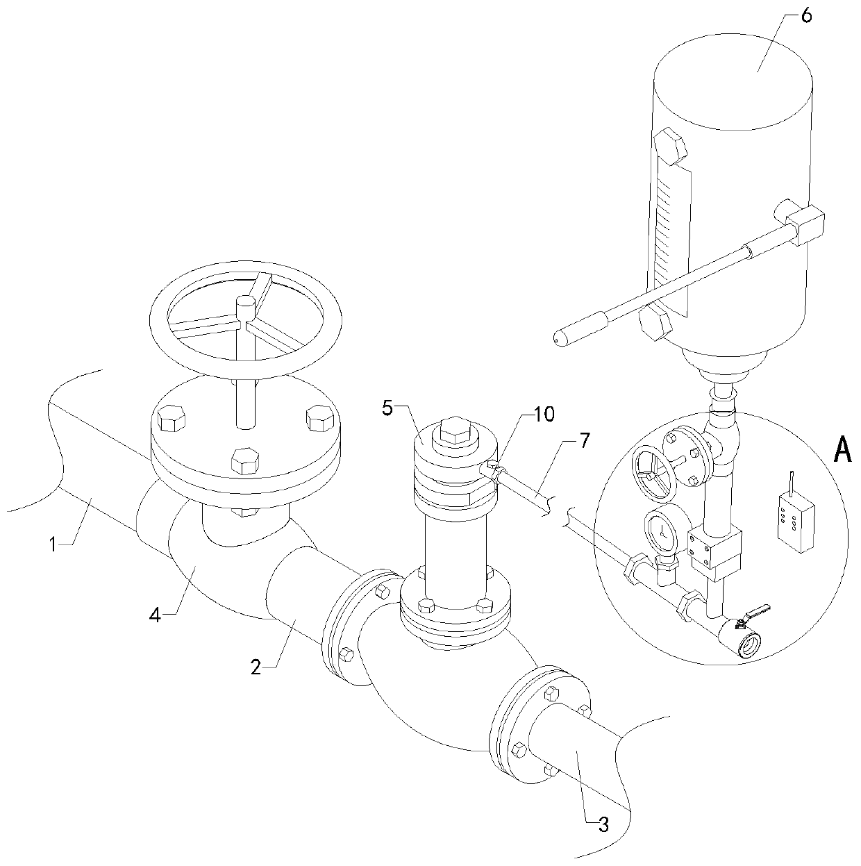

Image

  • Remote electromagnetic emergency cut-off device
  • Remote electromagnetic emergency cut-off device
  • Remote electromagnetic emergency cut-off device

Examples


Embodiment Construction

[0015] The specific implementation manners of the present invention will be further described in detail below in conjunction with the accompanying drawings and embodiments. The following examples are used to illustrate the present invention, but are not intended to limit the scope of the present invention.

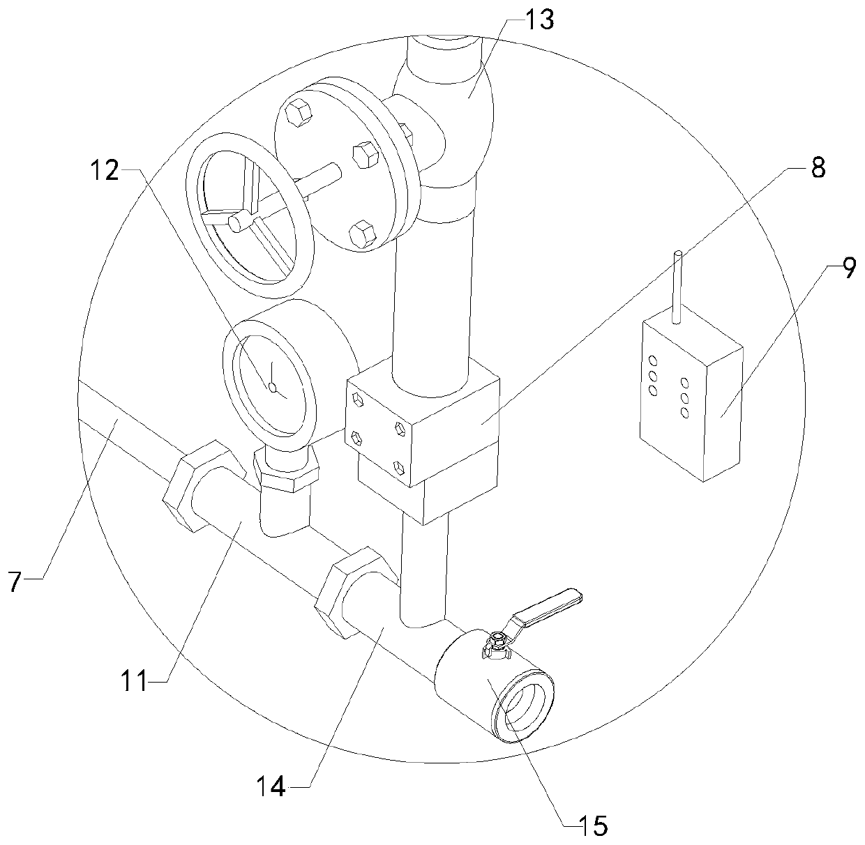
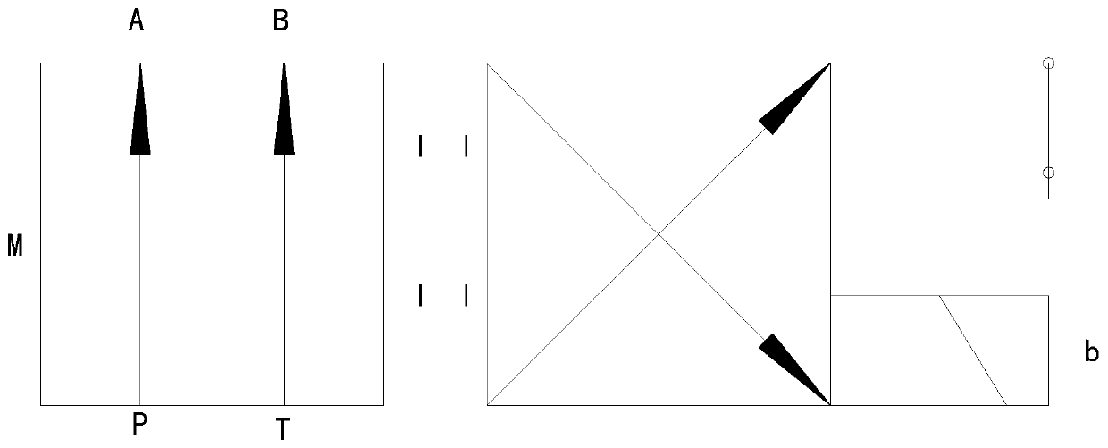
[0016] Such as Figure 1 to Figure 3 As shown, a remote control electromagnetic emergency cut-off device of the present invention includes a crane pipe 1, a connecting pipe 2 and a discharge pipe 3. The input end of the crane pipe 1 is provided with a first switch valve 4, and the output end of the connecting pipe 2 is connected to the first switch valve 4. The input end of a switching valve 4 is connected, and the output end of the discharge pipe 3 is connected with the input end of the connecting pipe 2; it also includes a hydraulic valve 5, a hand oil pump 6, a connecting pipe 7, a solenoid valve 8 and a hand-held remote control 9, The hand oil pump 6 is provided with ...


PUM


Abstract

The invention relates to the technical field of accessory devices of safety valves, in particular to a remote electromagnetic emergency cut-off device. The remote electromagnetic emergency cut-off device can realize a remote emergency cut-off function, is lower in cost and more convenient to manage. The remote electromagnetic emergency cut-off device includes a crane pipe, a connecting pipe and adischarge pipe, a first on-off valve is arranged at the input end of the crane pipe, the output end of the connecting pipe communicates with the input end of the first on-off valve, and the output endof the discharge pipe communicates with the input end of the connecting pipe. The remote electromagnetic emergency cut-off device further includes a hydraulic valve, a hand oil pump, a communicatingpipe, an electromagnetic valve and a hand-held remote control. The hand oil pump is provided with a rocker, the hydraulic valve is fixedly arranged on the connecting pipe, the hydraulic valve is provided with an oil delivery pipe, the output end of the hand oil pump communicates with the input end of the electromagnetic valve, the output end of the electromagnetic valve communicates with the inputend of the communicating pipe, the output end of the communicating pipe communicates with the input end of the oil delivery pipe, and the hand-held remote control is connected with the electromagnetic valve through an electrical signal.

Description

technical field [0001] The invention relates to the technical field of safety valve attachments, in particular to a remote-controlled electromagnetic emergency cut-off device. Background technique [0002] As we all know, when the liquid chlorine transport tank truck is unloaded, it is necessary to connect the crane pipe connected with the chlorine gas storage tank with the discharge pipe of the liquid chlorine tank truck. The crane pipe is provided with a switch valve, and the input end of the switch valve is provided with a connecting pipe. The unloading pipe is connected. When an accident such as liquid chlorine leakage occurs at the liquid chlorine transport tank, the on-off valve needs to be closed manually. Accidents, currently there is a device on the market that uses an electric valve to connect with the PLC system at the connecting pipe for remote control to realize emergency cut-off, but the electric valve and the supporting PLC system are expensive and require hig...

Claims


Application Information

Patent Timeline
Patent Type & Authority Applications(China)
IPC IPC(8): B67D7/52
CPCB67D7/52
Inventor 赵兰达宫敬海周书映单小兵赵文智单希任赵兰彬赵兰文任红强褚亚楠
Owner 沧州兴达化工有限责任公司
Learn More