Water-proof structure for civil engineering expansion joint

A civil engineering and waterproof structure technology, applied in bridge parts, bridges, buildings, etc., can solve problems such as expansion joint leakage, bridge deck damage, and corrosion bridge decks.

Active Publication Date: 2020-02-11
ZHENGZHOU UNIV OF IND TECH
View PDF20 Cites 1 Cited by
  • Summary
  • Abstract
  • Description
  • Claims
  • Application Information

AI Technical Summary

Problems solved by technology

[0005] In order to solve the defects of the prior art, the present invention provides a waterproof structure for expansion joints in civil engineering, which effectively solves the problems in the prior art that the expansion joints leak water, the water flow corrodes the bridge deck, and causes damage to the bridge deck. If the joints are in normal state, the deformation between the bridges will make the expansion joints bigger and smaller. When it rains, water may leak from the expansion joints and cause damage to the bridge deck. This civil engineering expansion joint waterproof structure will affect the expansion joints. The joints are closed to prevent water from flowing from the expansion joints to the underside of the pier, which protects the pier and ultimately does not affect the deformation between the bridges

Method used


Image

  • Water-proof structure for civil engineering expansion joint
  • Water-proof structure for civil engineering expansion joint
  • Water-proof structure for civil engineering expansion joint

Examples


Embodiment 1

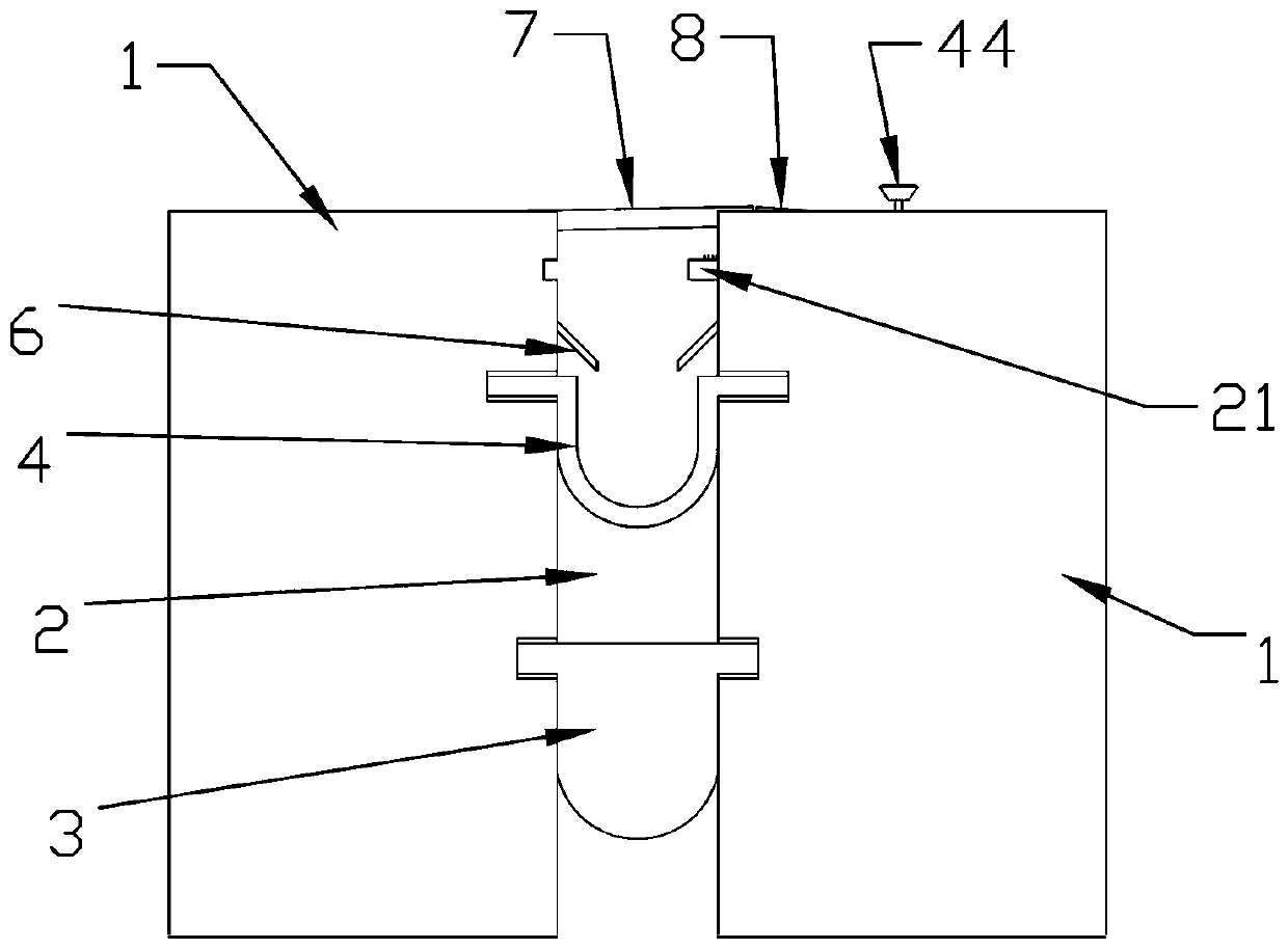
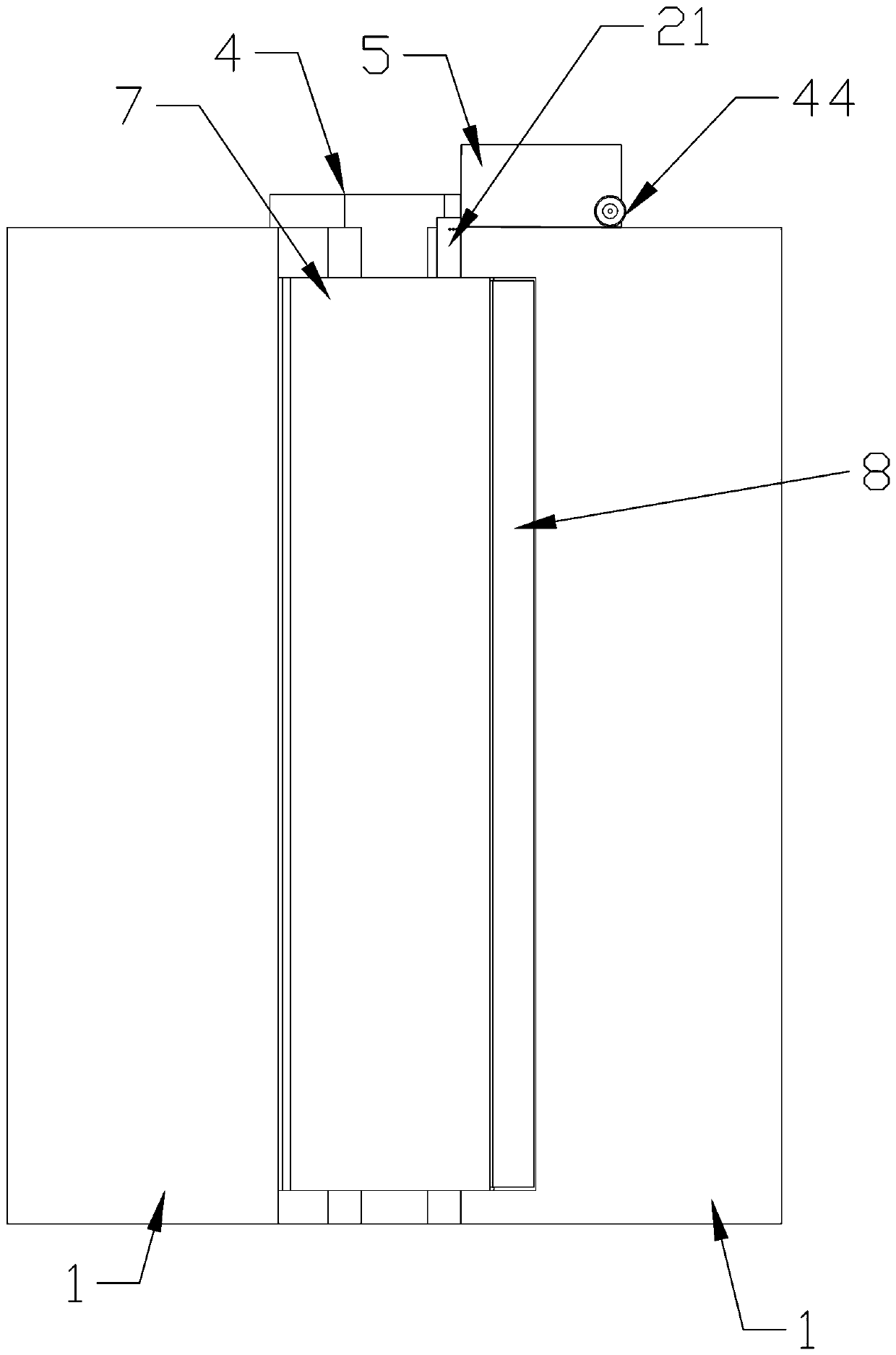
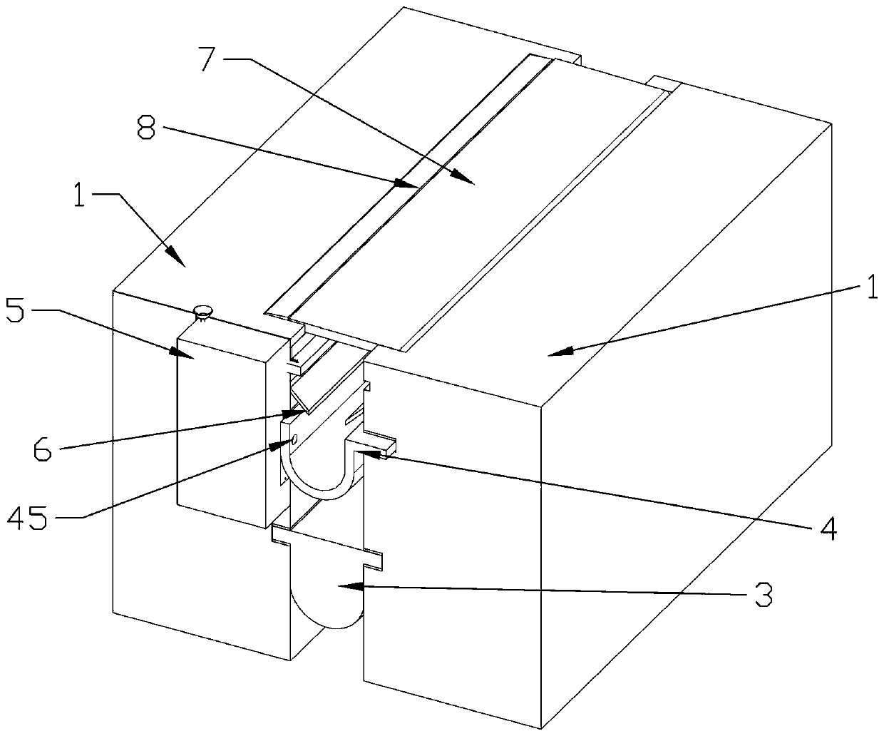
[0039] Embodiment 1, civil engineering expansion joint 2 waterproof structure, the rubber stopper 3 installed in the expansion joint 2 between two bridges 1, the gap between the bridges 1 is the expansion joint 2, and the rubber stopper 3 is fixed and embedded in the cement At the opposite ends of the two sections of the bridge 1, water droplets are prevented from penetrating into the pier below, and the rubber material will not affect the deformation of the bridge 1 after being heated and cooled. A rubber stopper 3 is installed above the two sections of the bridge 1 The drainage board 4, one end of the drainage board 4 protrudes outside the bridge 1, when the water flows out, it will not flow to the top of the bridge 1, the middle of the drainage board 4 is sunken downward, forming an arc shape, and has elasticity, so that the bridge 1 is deformed When the bridge 1 is deformed, it will not prevent the deformation of the bridge 1. When the water drips from the top, it can flow ...

Embodiment 2

[0047] Embodiment 2, on the basis of Embodiment 1, the lower end of the cylindrical surface of the power storage column 31 has a clamping gap 10 facing the left, and the clamping gap 10 is located at the bottom end of the cylindrical surface of the power storage column 31, a row of In the power storage shell 32 on the left side of the power storage column 31, there is a clamping column 11 that can slide longitudinally in the power storage shell 32. The clamping column 11 is in the shape of a cuboid and is slidably connected in the power storage shell 32. The right end of the column 11 is placed with some clamping buttons 12 that cooperate with the clamping notch 10, and the clamping buttons 12 are connected in the clamping groove 14 at the right end of the clamping column 11 through the clamping spring 13, and the clamping buttons 12 can pass through The clamping spring 13 stretches out and retracts in the clamping groove 14. The upper end of the clamping button 12 has rounded ...

Embodiment 3

[0049] Embodiment 3, on the basis of Embodiment 2, two sets of push plates 23 that cooperate with the clamping shell 15 are placed on the rear end of the closing plate 21, and the outer circle of the clamping shell 15 has a circle of rotating plates, and the pushing The plate 23 is rotatably connected in the push groove 24 in the closed plate 21, a set of said push plates 23 is placed on the right side of the closed plate 21, the right end surface of the push plate 23 is against the right side wall of the push groove 24, and the set Described push plate 23 right sides are connected on the closure plate 21 by inclined push spring 25, and one section of push spring 25 connects seal plate 21, and the other end connects push plate 23, and normal state is due to the existence of push spring 25. Pushing plate 23 is in vertical state, and when closing plate 21 moves to the left and contacts rotating plate, pushing plate 23 can not rotate, and when closing plate 21 has moved to and con...


PUM


Abstract

The invention provides a water-proof structure for a civil engineering expansion joint. A sealing plate embedded between two sections of bridges is used, and force accumulation torsional springs are subjected to self force accumulation for a passing vehicle through the force accumulation torsional springs so as to accumulate force for pushing the sealing plate is accumulated. During heavy rain, rain water flows into a water discharging plate in the expansion joint to enter a water receiving bucket. Through a clamping device, the internal force of the force accumulation torsional springs is released to push the sealing plate to seal the expansion joint between two sections of bridges, the rain water can not enter the lower end of the bridge through the expansion joint, and a pier on the lower end of the bridge can not be corroded. The water-proof structure disclosed by the invention is artful, can be produced on batch, performs a water-proof function on the expansion joint in the bridge, and protects the pier on the lower end of the bridge.

Description

technical field [0001] The invention relates to civil engineering devices, in particular to a waterproof structure for civil engineering expansion joints. Background technique [0002] Expansion joint refers to a structural joint vertically set along the appropriate part of the building length to prevent the structure from cracking or being damaged due to climate temperature changes (thermal expansion, cold contraction). The expansion joint is to divide the building components above the foundation such as walls, floors, roofs (except wooden roofs) into two independent parts, so that the building can be horizontally expanded along the long direction. [0003] Many kinds of bridge expansion joints are used in bridge construction in our country, and most of them leak water. Therefore, in the bridges built before, the girder ends and cap beams under the expansion joints are most seriously damaged by water. Since it is difficult to ensure that the expansion joint is completely ...

Claims


Application Information

Patent Timeline
Patent Type & Authority Applications(China)
IPC IPC(8): E01D19/06E01D19/08
CPCE01D19/06E01D19/083
Inventor 崔秀丽刘庆苗方利李冉陈靖吴亚敏
Owner ZHENGZHOU UNIV OF IND TECH
Why Eureka
Try Eureka