
Construction method of inverted-splayed cast-in-place arc-shaped wing web formwork system

A construction method, the inverted horoscope technology, applied in the erection/assembly of bridges, bridges, buildings, etc., can solve the problems that steel molds are easily affected by weather and humidity, increase the difficulty of formwork assembly, increase construction labor costs, etc., and achieve the setting of the wing plate Convenient support, reduce mechanical noise pollution, and reduce the effect of customization process

Inactive Publication Date: 2020-02-11
CCFEB CIVIL ENG
View PDF5 Cites 1 Cited by
  • Summary
  • Abstract
  • Description
  • Claims
  • Application Information

AI Technical Summary

Problems solved by technology

But it still has deficiencies: (1) this invention is a kind of prestressed concrete variable section construction method, has adopted custom-made steel formwork in a large number, and steel material consumption is big, and assembly process order must strictly abide by steel formwork number sequence, steel formwork The number is worn, which increases the difficulty of template assembly
(3) The steel mold in this invention is more easily affected by the weather and humidity, and is easy to rust. It must be derusted and polished before the mold is assembled in the later stage, which increases the construction labor cost

Method used


Image

  • Construction method of inverted-splayed cast-in-place arc-shaped wing web formwork system
  • Construction method of inverted-splayed cast-in-place arc-shaped wing web formwork system
  • Construction method of inverted-splayed cast-in-place arc-shaped wing web formwork system

Examples


Embodiment

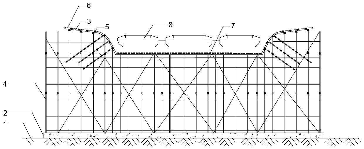
[0026] For the construction method of the inverted splayed cast-in-place curved wing web formwork system, please refer to figure 1 , figure 2 , image 3 , Figure 4 , including the following steps:

[0027] (1) Site leveling and foundation treatment

[0028] Lay a 10-15m thick C20 concrete cushion on the foundation and build drainage ditches on both sides of the foundation, and control the degree of compaction of the foundation to ≥93%;

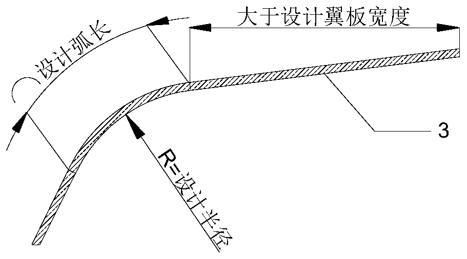
[0029] (2) Bending curved steel pipe

[0030] see image 3 , the curved steel pipe is made of Φ48*3.5mm steel pipe. Specifically, according to the size of the box girder and the reserved length, calculate and determine the arc length, radius, arc starting point and arc end point of the curved steel pipe, and the arc end point and the end of the curved steel pipe The distance should be greater than the design width of the wing plate; use the steel bar bending machine on the market, set the axis of the bending machine as the center, put ...


PUM


Abstract

The invention discloses a construction method of an inverted-splayed cast-in-place arc-shaped wing web formwork system. The construction method is characterized by comprising the following steps of (1) site leveling and foundation treatment; (2) bending of bent steel pipes; (3) erecting of a full type bowl-buckle scaffold; (4) bottom formwork mounting and support prepressing; (5) wing plate formwork mounting; (6) inelastic deformation eliminating; (7) elastic deformation measuring; and (8) steel bar mounting and inner formwork splicing. According to the construction method, a box girder formwork system is formed by adopting bowl-buckle scaffold wood formworks, steel pipe bending is completed through an existing bending machine, and an arc-shaped wing plate formwork system is formed by replacing a heavy steel formwork with bamboo plywood, so that the advantages of space and time can be better utilized, and the purpose of rapid construction is achieved.

Description

technical field [0001] The invention belongs to the technical field of bridge construction, and in particular relates to a construction method of an inverted splayed cast-in-place curved wing web formwork system. Background technique [0002] There are various forms of bridge design, and the cross-section of modern bridges has the characteristics of gradual change. Most construction companies use custom-made steel molds for construction during the construction process. For small-scale bridges, the cost of steel molds increases significantly. On the one hand, steel molds have the defect of non-repeatable turnover; Large, high hoisting technical requirements, easy to cause safety accidents. [0003] The existing technology close to the present invention is the Chinese invention patent (application number 201610101083.2), which relates to a construction method of prestressed concrete variable cross-section continuous box girder, which involves multiple construction procedures,...

Claims


Application Information

Patent Timeline
Patent Type & Authority Applications(China)
IPC IPC(8): E01D21/00
CPCE01D21/00
Inventor 黄剑颖覃晓滨雷苗华岳文飞张胥石振
Owner CCFEB CIVIL ENG
Learn More