Load-deflection resistance side pressing cylinder device

An anti-eccentric load and side-holding cylinder technology is applied in the field of hydraulic presses, which can solve the problems that the side-holding cylinder does not have anti-eccentric load measures, increased production and maintenance costs, hidden safety hazards, etc., so as to facilitate continuous work, reduce safety hazards, and increase use. effect of life

Active Publication Date: 2020-02-11
HEFEI METALFORMING MACHINE TOOL
View PDF8 Cites 1 Cited by
  • Summary
  • Abstract
  • Description
  • Claims
  • Application Information

AI Technical Summary

Problems solved by technology

[0004] Aiming at the deficiencies of the prior art, the present invention provides an anti-eccentric load side cylinder device, which has anti-eccentric load measures, effectively protects the plunger rod of the oil cylinder, and is not prone to the phenomenon of roughening of the plunger rod of the side pressure cylinder or the sliding block Accidents such as broken connecting screws directly lead to increased production and maintenance costs and potential safety hazards. It solves the problem that the blank holder cylinder does not have anti-eccentric load measures. Accidents such as roughening of the plunger rod of the side cylinder or breakage of the connecting screw with the slider directly lead to an increase in production and maintenance costs and potential safety hazards

Method used


Image

  • Load-deflection resistance side pressing cylinder device
  • Load-deflection resistance side pressing cylinder device
  • Load-deflection resistance side pressing cylinder device

Examples


Embodiment 1

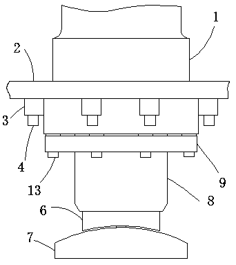
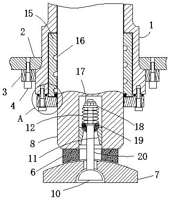
[0023] The anti-bias load side cylinder device includes a fixed frame 2, an oil cylinder body 1, a plunger rod 8 and a guide copper sleeve 15. The lower end of the oil cylinder body 1 is provided with an opening, and the upper end of the plunger rod 8 passes through the opening and connects with the oil cylinder body 1. The inner wall of the plunger rod 8 is slidingly socketed, and the lower end of the plunger rod 8 is provided with a cylindrical groove, and an anti-eccentric load mechanism is provided in the cylindrical groove, and the plunger rod 8 is connected with the lower spherical pad 7 through the anti-eccentric load mechanism. The inner edge is provided with an annular slot, and the oil cylinder body 1 is engaged with the outer wall of the guide copper sleeve 15 through the annular slot. The guide copper sleeve 15 and the annular slot are in an interference connection. The oil groove 16, the lubricating oil groove 16 and the rod wall of the plunger rod 8 jointly form a...

Embodiment 2

[0026] Embodiment 2: the difference based on Embodiment 1 is;

[0027] The anti-bias load mechanism includes an annular block 6 fixed on the lower end of the plunger rod 8. The opening edge of the lower end of the annular block 6 is provided with a concave surface matching the upper end of the lower spherical pad 7, and the center of the lower end of the lower spherical pad 7 is provided with a hemispherical concave. Groove, the first hemisphere 10 is slidingly connected in the hemispherical groove, the upper center of the first hemisphere 10 is screwed with the pull rod 20 through the first threaded hole, and the transition sleeve 11 is fixedly connected in the cylindrical groove, and the transition sleeve 11 The inner side is a frustum-shaped structure. The upper end of the pull rod 20 passes through the annular block 6 and the transition sleeve 11 and is sleeved with a spring 12 and an annular gasket 18. The upper end of the pull rod 20 is threaded with a nut 17 through an e...

Embodiment 3

[0030] Embodiment 3: the difference based on embodiment 1 is;

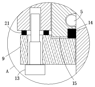
[0031]The sealing mechanism includes a sealing pressure ring 9 slidingly sleeved on the wall of the plunger rod 8. The lower end edge of the sealing pressure ring 9 is slidably sleeved with a plurality of fixing bolts 13 through through holes, and the lower end edge of the oil cylinder body 1 is through multiple bolts. A second threaded hole is threadedly connected with a plurality of fixing bolts 13 respectively, and the inner opening of the upper end of the sealing pressure ring 9 is provided with a positioning slot matched with the lower end of the guide copper sleeve 15, and the inner edge of the lower end opening of the guide copper sleeve 15 A sealing ring 14 is embedded, and the inner side of the sealing ring 14 is slidingly socketed with the rod wall of the plunger rod 8 .

[0032] The upper end of the sealing pressure ring 9 is provided with a plurality of adjusting washers 21, and the plurality of adjust...


PUM


Abstract

The invention relates to the technical field of hydraulic machines, and discloses a load-deflection resistance side pressing cylinder device. The device comprises a fixed frame, an oil cylinder body,a plunger rod and a guide copper sleeve. An opening is formed in the lower end of the oil cylinder body, the upper end of the plunger rod penetrates through the opening and is slidingly sleeved with the inner wall of the oil cylinder body, a cylinder groove is formed in the lower end of the plunger rod, a load-deflection resistance mechanism is arranged in the cylinder groove, the plunger rod is connected with a lower spherical gasket through the load-deflection resistance mechanism, an annular clamping groove is formed in the inner edge of the opening in the lower end of the oil cylinder body, the oil cylinder body is clamped with the outer wall of the guide copper sleeve through the annular clamping groove, a lubricating oil groove of a spiral structure is formed in the guide copper sleeve, and a lubricating channel is jointly formed by the lubricating oil groove and the rod wall of the plunger rod. Due to the load-deflection resistance side pressing cylinder device, the plunger rodof the oil cylinder can be effectively protected, the napping phenomenon of the plunger rod of the side pressing oil cylinder or/and accidents like breaking of a connecting screw of a sliding block are not prone to happening, the maintaining cost can be reduced, and the safety hidden danger during use of the edge pressing oil cylinder can be reduced.

Description

technical field [0001] The invention relates to the technical field of hydraulic presses, in particular to an anti-eccentric load blanking cylinder device. Background technique [0002] The double-acting hydraulic press is mainly used for thin plate stretching, bending, forming and other processes, and can also be used for plastic pressing, cold extrusion bending, forming correction and press-fitting. The edge cylinder of the double-action hydraulic press can be used as a buffer device, and can also be used for blanking and punching. Under the pressure set by the system, the working pressure of each cavity can be adjusted separately. In order to ensure the quality of stretching and blank holder, a pressure maintaining system of blank holder cylinder is added. However, the existing double-acting hydraulic pressure press cylinder does not have anti-eccentric load measures. Accidents such as roughening of the plunger rod of the edge-holding cylinder or breakage of the connecti...

Claims


Application Information

Patent Timeline
Patent Type & Authority Applications(China)
IPC IPC(8): F15B15/14F15B15/20F16N1/00B30B15/28B30B1/32
CPCB30B1/32B30B15/28F15B15/1423F15B15/1428F16N1/00
Inventor 王玉山李卫华崖华青李贵闪王芝发陈幼筠许亮穆亚飞张亭余志海
Owner HEFEI METALFORMING MACHINE TOOL
Why Eureka
Try Eureka