Network equipment protection frame

A technology of network equipment and protective frame, which is applied in the direction of mechanical equipment, electrical equipment structural parts, electrical equipment shell/cabinets/drawers, etc., which can solve problems such as troublesome installation and disassembly, low flexibility, and poor heat dissipation, and achieve The effect of preventing damage to equipment, good heat dissipation, and easy movement of the main body of the device

Active Publication Date: 2020-02-11
山东沂南园区开发建设有限公司
View PDF8 Cites 2 Cited by
  • Summary
  • Abstract
  • Description
  • Claims
  • Application Information

AI Technical Summary

Problems solved by technology

[0004] The purpose of the present invention is to provide a protection frame for network equipment in order to solve the problems (not high flexibility, troublesome installation and disassembly process, poor heat dissipation)

Method used


Image

  • Network equipment protection frame
  • Network equipment protection frame
  • Network equipment protection frame

Examples


Embodiment Construction

[0034] In order to make the object, technical solution and advantages of the present invention clearer, the present invention will be further described in detail below in conjunction with the accompanying drawings and embodiments. It should be understood that the specific embodiments described here are only used to explain the present invention, not to limit the present invention.

[0035]In the description of the present invention, it should be noted that the terms "center", "upper", "lower", "left", "right", "vertical", "horizontal", "inner", "outer" etc. The indicated orientation or positional relationship is based on the orientation or positional relationship shown in the drawings, and is only for the convenience of describing the present invention and simplifying the description, rather than indicating or implying that the referred device or element must have a specific orientation, or in a specific orientation. construction and operation, and therefore cannot be construe...


PUM


Abstract

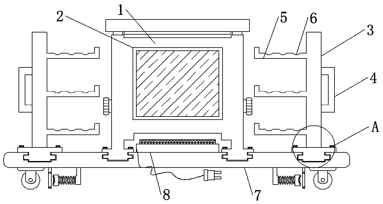
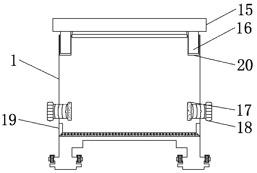
The invention discloses a network equipment protection frame, which comprises a protection box, a device base and a heat dissipation chamber, wherein the bottom of the protection box is fixedly connected with the device base; the heat dissipation chamber is fixedly connected to the middle of the top of the device base; rollers are fixedly connected to the bottom of the device base; the other sideof the roller is fixedly connected with a limiting bolt; the other side of the limiting bolt is fixedly connected with an elastic brake rod; the top of the protection box is fixedly connected with a box cover; one side of the bottom of the box cover is fixedly connected with a limiting rod; a network equipment limiting bolt is connected to one side of the protection box in an embedded manner; thenetwork equipment limiting bolt prevents the network equipment from shaking in the moving process of the protection frame. The practicability of the device body is improved through a visual window, the heat dissipation performance of the device body is improved through heat dissipation holes, the flexibility of the device body is improved through the moving mechanism, the working efficiency of workers is improved through the detachable network equipment protection mechanism, and the network equipment protection frame is suitable for network equipment protection and has a wide development prospect in the future.

Description

technical field [0001] The invention belongs to the technical field of network equipment protection, in particular to a network equipment protection frame. Background technique [0002] With the development of the IT industry, network equipment is getting deeper and deeper into every corner of social life. At present, a large number of network devices are generally installed in a network case, and various devices are arranged through the network case, which plays a role of security protection for the devices installed inside. [0003] The existing network equipment protection frame is not very flexible, and the staff cannot move the main body of the device flexibly, which leads to certain limitations in the use of the device body. The installation and disassembly process of the existing network equipment protection frame is cumbersome, which seriously affects the The work efficiency of the staff, the network equipment protection frame takes up a lot of space when not in use...

Claims


Application Information

Patent Timeline
Patent Type & Authority Applications(China)
IPC IPC(8): H05K5/02H05K7/14H05K7/20F16M3/00F16M7/00
CPCF16M3/00F16M7/00H05K5/0217H05K5/0234H05K7/14H05K7/20136H05K7/20172
Inventor 郑晓精
Owner 山东沂南园区开发建设有限公司
Why Eureka
Try Eureka