
Inhaul cable power device, power system and power assisting equipment thereof, and control method of power assisting equipment

A power device and power system technology, applied in passive exercise equipment, physical therapy, etc., can solve problems such as poor wearing experience, bulky devices, discomfort, etc., and achieve simplified design complexity, high space utilization, and good durability Effect

Active Publication Date: 2020-02-14
SHENZHEN CONCHIN TECH CO LTD
View PDF13 Cites 2 Cited by
  • Summary
  • Abstract
  • Description
  • Claims
  • Application Information

AI Technical Summary

Problems solved by technology

[0002] Human beings often encounter the situation of wishing to enhance the strength of human legs in daily work and life. Wearable exoskeleton robots are devices that meet this type of application, especially powered lower limb-assisted exoskeleton robots; Such devices are usually cumbersome, such as patent 200680006514.1 and patent 200780027195.7 all disclose this type of technology, and users of devices using this technology have poor wearing experience
[0003] In the prior art, there is a device specially designed to assist the knee joint. This type of device is substantially tailored for the above-mentioned bulky equipment, thereby greatly reducing the weight of the equipment. Patents US9532894B2 and CN2018103683215 both disclose a technology for assisting the knee joint. The use of a relatively portable power-assisted device to assist the wearer's lower limbs has greatly improved the user's wearing experience; but this type of technology also has obvious defects: the power device is placed at the knee joint, and the motor and reducer included in the power device And the related transmission mechanism will bring weight. The weight of the power device increases the weight and inertia of the wearer's legs. This type of device does not have power assist in the hip joint. The wearer will feel uncomfortable when lifting the leg or going upstairs, resulting in long-term wearing poor experience

Method used


Image

  • Inhaul cable power device, power system and power assisting equipment thereof, and control method of power assisting equipment
  • Inhaul cable power device, power system and power assisting equipment thereof, and control method of power assisting equipment
  • Inhaul cable power device, power system and power assisting equipment thereof, and control method of power assisting equipment

Examples


Embodiment 2

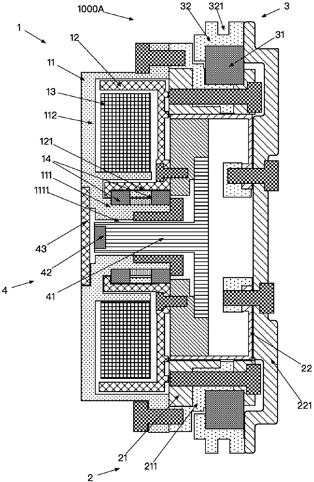
[0086] Such as figure 2 Shown is the structural diagram of Embodiment 2, and the difference from Embodiment 1 lies in the encoder mechanism 4 . The inner end of the central beam 41 of the encoder mechanism 4 is fixedly connected with the deceleration generator 23, and extends to the edge of the motor stator casing 11 through the stator central through hole 1111, and the first magnet 42 is fixed on the outer end of the central beam 41 Above, the first magnetic field induction circuit 43 is fixed on the motor stator casing 11 and is close to the first magnet 42 . Its working principle is identical with embodiment 1. The concave cavity of the rotary wheel 22 is made shallower by adopting the scheme of embodiment 2, thereby reducing the thickness and volume of the device as a whole.

[0087] The present invention is a cable driving power system, Figure 1 to Figure 7 As shown, the knee joint part includes a thigh rod 1000D, a knee joint turntable 1000B, a cable 1000C, a cable ...

Embodiment 1

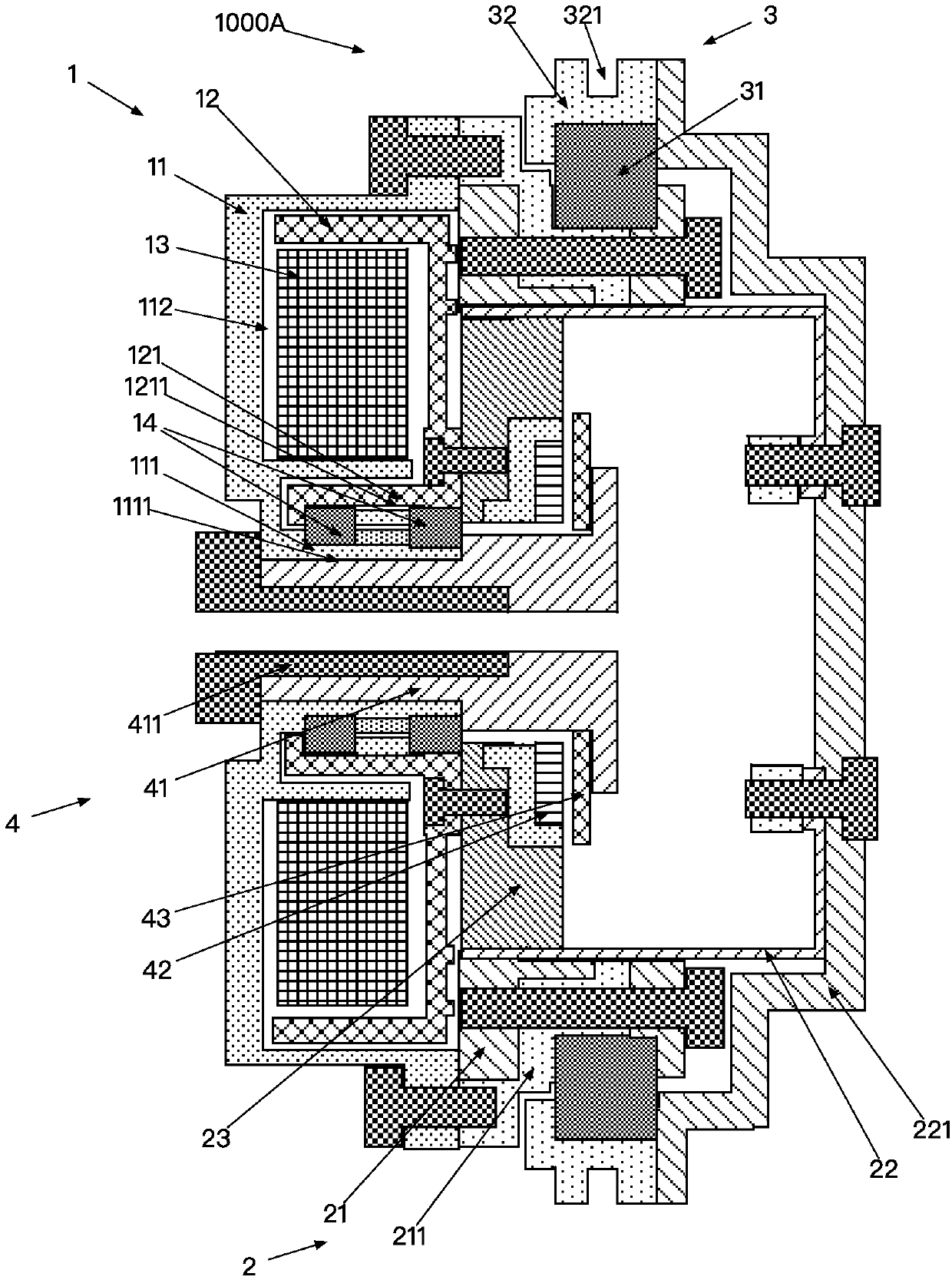
[0097] Embodiment 1: a kind of portable booster equipment, such as Figure 9-10 As shown, it includes a power system 1000 , an energy system 1001 , a control system 1002 , a human-machine connection 1003 and a motion sensing system 1004 . The power system is the above-mentioned cable-driven power system; the control system controls the tension or relaxation of the cables of the cable-driven power system, thereby controlling the extension or bending of the wearer's lower limbs.

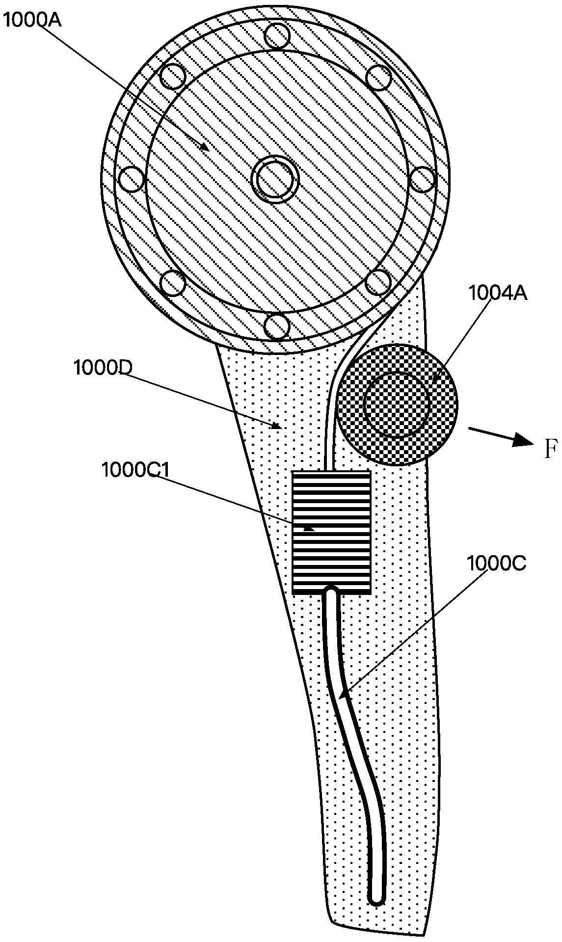
[0098] The power system 1000 includes a compact cable power drive device 1000A of the present invention, a knee joint turntable 1000B, a cable 1000C, a thigh rod 1000D, a calf rod 1000E, a waist connecting section 1000F, and a hip joint 1000G; the waist connecting section 1000F and The thigh rod 1000D is rotatably connected through the hip joint 1000G, the thigh rod 1000D is rotatably connected with the calf rod 1000E through the power knee joint 1000B, the power drive device 1000A is fixed on the thig...

Embodiment 3

[0105] Example 3, such as Figure 13As shown, compared with the embodiment 2, the embodiment 3 does not set an idler wheel at the hip joint 1000G, and the cable 1000C is directly connected to the knee joint turntable 1000B from the waist of the wearer. Since the cable 1000C adopts The Bowden line allows the shell to bend and swing when transmitting tension, so it can transmit power while walking on the legs. Embodiment 3 has a simplified structure compared to Embodiment 2, and it is especially suitable for transmission of a small pulling force; when the pulling force of the cable is relatively large, the shell of the cable 1000C is relatively hard and difficult to bend, which cannot meet the needs of human lower limbs for walking .

[0106] Figure 9 to Figure 13 What is shown is only the case of wearing on one leg. The portable booster device of the present invention can be used on one leg or on both legs.

[0107] Such as Figure 14 to Figure 18 Drawings for the control ...


PUM


Abstract

The invention relates to an inhaul cable power device, a power system, power assisting equipment, and a control method of the power assisting equipment. According to the inhaul cable driving power device, by adopting a simplified harmonic speed reducer, a power piece is transmitted to an inhaul cable driving mechanism through the simplified harmonic speed reducer, so that the purposes of reducingthe weight of a power joint and improving the energy density are achieved. According to a power system based on the inhaul cable driving power device, power is output in an inhaul cable transmission mode, and therefore the power device can be moved upwards to a position near the waist of a wearer, leg inertia is reduced, damage to the knee joint is reduced, and the purpose of improving wearing flexibility and maneuverability is achieved. The portable power assisting equipment based on the power system helps a control system of the power assisting equipment to improve the exoskeleton power performance, can provide assistance for the knee joint and the hip joint of the wearer, and is low in cost and high in reliability.

Description

technical field [0001] The present invention relates to wearable equipment, more specifically to a cable power device and its power system, power-assisted equipment and its control method. Background technique [0002] Human beings often encounter the situation of wishing to enhance the strength of human legs in daily work and life. Wearable exoskeleton robots are devices that meet this type of application, especially powered lower limb-assisted exoskeleton robots; Such devices are usually bulky, such as patent 200680006514.1 and patent 200780027195.7 all disclose this type of technology, and users of devices using this technology have poor wearing experience. [0003] In the prior art, there is a device specially designed to assist the knee joint. This type of device is substantially tailored for the above-mentioned bulky equipment, thereby greatly reducing the weight of the equipment. Patents US9532894B2 and CN2018103683215 both disclose a technology for assisting the knee...

Claims


Application Information

Patent Timeline
IPC IPC(8): A61H1/02
CPCA61H1/024A61H1/0218A61H2201/165A61H2201/1659A61H2201/5061A61H2201/5069
Inventor 不公告发明人
Owner SHENZHEN CONCHIN TECH CO LTD
Learn More