A dynamic joint device and lower limb assisting equipment

A technology for power devices and joints, applied in the field of wearable devices, can solve the problems of high cost, large size of the torque sensor, and no disclosure of installation accuracy.

Active Publication Date: 2021-05-18
SHENZHEN CONCHIN TECH CO LTD
View PDF14 Cites 0 Cited by
  • Summary
  • Abstract
  • Description
  • Claims
  • Application Information

AI Technical Summary

Problems solved by technology

In terms of the connection structure of the upper arm and the lower arm, in order to simplify the design, some schemes fix the upper arm and the lower arm with the flexible wheel and the steel wheel of the harmonic reducer respectively, such as the 2011 master thesis of Harbin Institute of Technology "Exoskeleton lower limb power-assisted robot This scheme is disclosed in "Technical Research", which will cause the upper and lower arms to be out of the same plane, and a large overturning torque will be generated when the joint bears force, which is easy to damage the joint; the paper "Mechanical Design of the Hanyang Exoskeleton Assistive Robot (HEXAR)" ICCAS2014 also A similar scheme is disclosed; in order to reduce the influence of the overturning torque in the above scheme, crossed roller bearings can be used. The cost of this scheme is relatively high, but the structural rigidity is still not good
[0004] In the prior art, a rotary encoder is required to control the motor, and the existing solutions all use photoelectric rotary encoders, which are large in size and high in cost, resulting in complicated design of dynamic joints; the paper "Mechanical Design of the Hanyang Exoskeleton Assistive Robot (HEXAR)" ICCAS2014, The paper "Design of an electrically actuated lower extremity exoskeleton" (Advanced Robotics, Vol.20, No.9, pp.967–988 (2006)) and Chinese patent 201620267410.7 both disclose the same scheme
[0005] In the prior art, some torque sensors are used to measure the output torque of the motor. For example, the paper "Mechanical Design of the Hanyang Exoskeleton Assistive Robot (HEXAR)" ICCAS2014 discloses such a scheme. This scheme has strict requirements for installation accuracy, which is difficult to guarantee in the actual environment. The paper does not disclose how to solve the problem of installation accuracy; some use pressure sensors to measure the output torque of the motor, the paper "Design of electrically actuated lower extremity exoskeleton" (Advanced Robotics, Vol.20, No.9, pp.967–988 (2006)) This kind of scheme is disclosed in . The structure of this scheme is relatively complicated, the requirements for installation accuracy are very strict, and the cost is relatively high. This scheme also fails to disclose how to ensure the installation accuracy
[0006] In the prior art, the dynamic joint does not include a solution for measuring the relative angle of the upper arm and the lower arm. Generally, the motor encoder is used to estimate the relative angle of the upper and lower arms. The problem with this solution is that calibration is required every time the power is turned on, and the accuracy is difficult to guarantee; The paper "Mechanical Design of the Hanyang Exoskeleton Assistive Robot (HEXAR)" ICCAS2014 and the paper "Design of an electrically actuated lower extremity exoskeleton" (Advanced Robotics, Vol.20, No.9, pp.967–988(2006)) did not disclose specific Solution for Measuring the Relative Angle of the Upper and Lower Arms
[0007] In the prior art, the patent 201611189733.X mentions a power joint device for exoskeleton, the device is equipped with a torque sensor, a motor encoder and an angle sensor. In this solution, there are gaps and large volumes in the structure of the torque sensor. Unsightly, the connecting part of the upper and lower arms and the harmonic reducer adopts a single-board structure, and it is difficult to achieve good rigidity under the same volume and weight

Method used


Image

  • A dynamic joint device and lower limb assisting equipment
  • A dynamic joint device and lower limb assisting equipment
  • A dynamic joint device and lower limb assisting equipment

Examples


Embodiment Construction

[0040] In order to fully understand the technical content of the present invention, the technical solutions of the present invention will be further introduced and illustrated below in conjunction with specific examples, but not limited thereto.

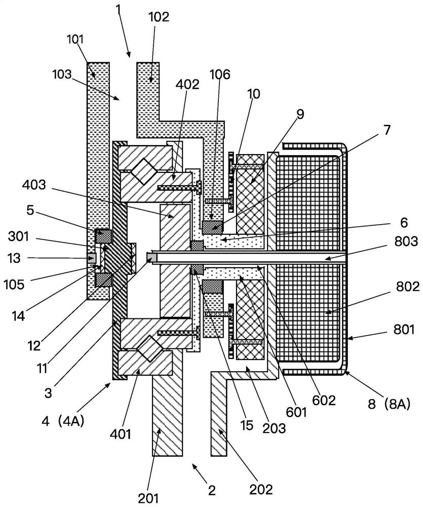
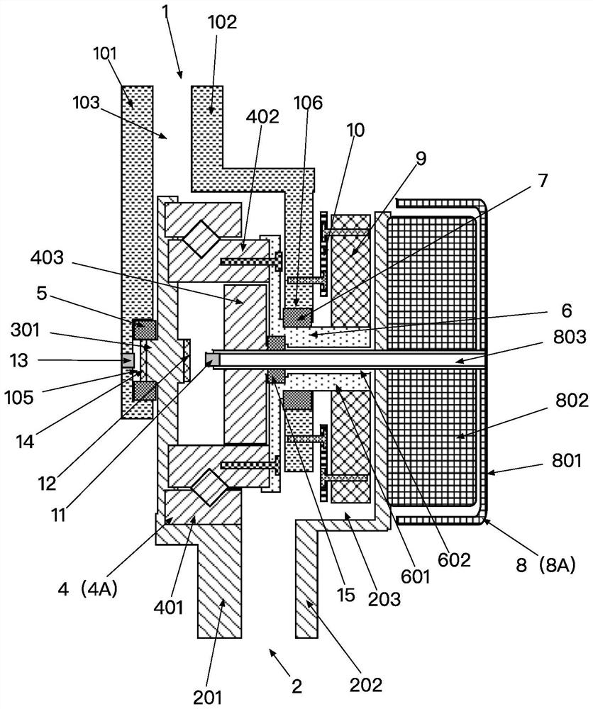
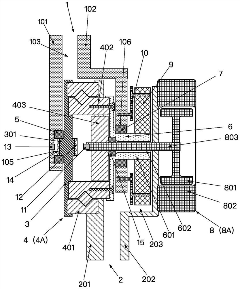
[0041] like figure 1 — Figure 8 Shown is a specific structural view of an embodiment of a portable dynamic joint device of the present invention.

[0042] A powered joint device such as figure 1 — image 3 As shown, it includes a joint body 1001 and a power device disposed on the joint body 1001 . The joint body 1001 includes an upper arm 1 and a lower arm 2 that moves relative to the upper arm 1 . The power device includes a power part 8A, and a reduction mechanism 4A fixed at the power output end of the power part 8A. The power part 8A is fixed on the lower arm 2, and the power output end of the reduction mechanism 4A is connected with the upper arm 1, so that the power part 8A drives the upper arm 1 to move relative to the lo...


PUM


Abstract

The invention discloses a dynamic joint device and lower limb assisting equipment. A dynamic joint device, comprising a joint main body and a power device arranged on the joint main body, the joint main body includes an upper arm, and a lower arm that moves relative to the upper arm; the power device includes a power part, and a deceleration mechanism fixed at the power output end of the power part; The power part is fixed on the lower arm, and the power output end of the reduction mechanism is connected with the upper arm, so that the power part drives the upper arm to move relative to the lower arm; or the power part is fixed on the upper arm, and the power output end of the reduction mechanism is connected with the lower arm, so that Make the lower arm move relative to the upper arm. And through the torque measuring mechanism, the first angle measuring mechanism, the second angle measuring mechanism and other data exchange with the control system, to control the rotation of the motor, so as to realize the controllability of the motor to the mutual rotation of the upper arm and the lower arm. Also, the reduction mechanism utilizes a harmonic reducer, which has a high number of reduction stages, a small volume, a simple structure, and low production costs.

Description

technical field [0001] The invention relates to the technical field of wearable devices, and more specifically refers to a dynamic joint device and a lower limb assisting device. Background technique [0002] The field of robotics requires the application of dynamic joints widely. The exoskeleton robots used for human wearables generally have multiple dynamic joints. It is also necessary to integrate force sensors, angle sensors, and motor rotary encoders; at the same time, it is also necessary for the dynamic joint to be small in size, light in weight, and low in cost. [0003] In the prior art, a flat disc motor is generally used for the motor, and a harmonic reducer is used for the reducer, so that the axial size of the power joint can be made smaller. In terms of the connection structure of the upper arm and the lower arm, in order to simplify the design, some schemes fix the upper arm and the lower arm with the flexible wheel and the steel wheel of the harmonic reducer...

Claims


Application Information

Patent Timeline
Patent Type & Authority Patents(China)
IPC IPC(8): B25J17/00B25J9/00
Inventor 不公告发明人
Owner SHENZHEN CONCHIN TECH CO LTD
Why Eureka
Try Eureka