Hydraulic oil tank with external filtering structure

A technology of hydraulic oil tank and filter structure, applied in the direction of oil supply tank device, fluid pressure actuating device, fluid pressure actuating system components, etc., can solve problems such as hidden safety hazards, high energy consumption, pollution of the surrounding environment, etc. , Easy to adjust, low energy consumption

Pending Publication Date: 2020-02-14
盐城市振升液压机械有限公司
View PDF0 Cites 0 Cited by
  • Summary
  • Abstract
  • Description
  • Claims
  • Application Information

AI Technical Summary

Problems solved by technology

[0004] The purpose of the present invention is to provide a hydraulic oil tank with an external filter structure to solve the problem that the existing hydraulic oil tank proposed in the above background technology can only play the role of precipitating impurities. The impurities in the hydraulic system gradually reduce the operating efficiency of the hydraulic system. The existing hydraulic oil tank is preheated by idling the engine in a cold environment. This preheating method consumes high energy and has low efficiency, and cannot quickly and effectively increase the temperature of the oil. , and the existing hydraulic oil tank will produce oil overflow in the case of operating errors, etc., the reason is that the overflow valve discharges oil to avoid cylinder explosion, but the discharged oil will pollute the surrounding environment, and the exposed oil will also have certain Potential safety hazard. The bottom of the existing hydraulic oil tank is flat. When replacing the oil, due to the viscosity of the oil, a part of the oil is easy to remain at the bottom of the hydraulic oil tank, which needs to be cleaned manually.

Method used


Image

  • Hydraulic oil tank with external filtering structure
  • Hydraulic oil tank with external filtering structure
  • Hydraulic oil tank with external filtering structure

Examples


Embodiment Construction

[0028] The following will clearly and completely describe the technical solutions in the embodiments of the present invention with reference to the accompanying drawings in the embodiments of the present invention. Obviously, the described embodiments are only some, not all, embodiments of the present invention. Based on the embodiments of the present invention, all other embodiments obtained by persons of ordinary skill in the art without making creative efforts belong to the protection scope of the present invention.

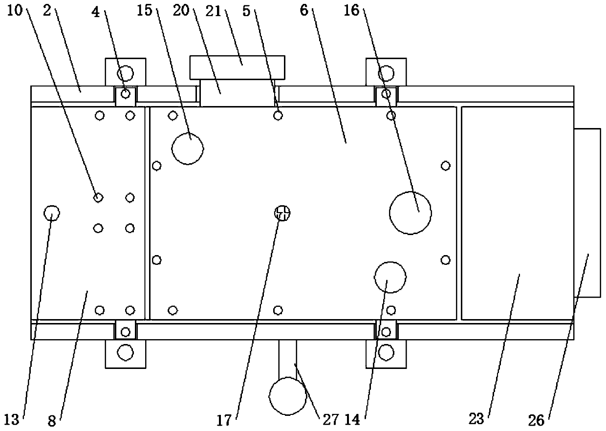
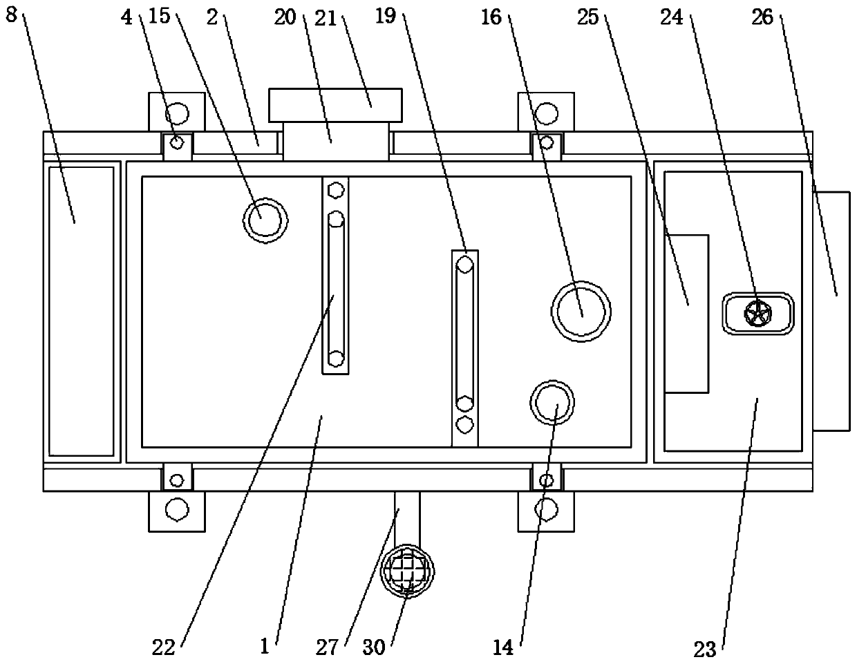
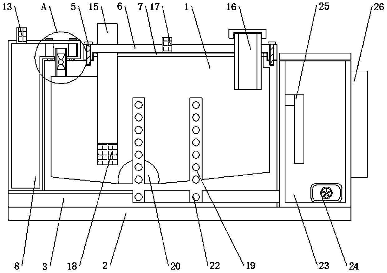
[0029] see Figure 1-7 , the present invention provides a technical solution: a hydraulic oil tank with an external filter structure, such as figure 1 , image 3 and Figure 4 As shown, a bracket 2 is arranged outside the bottom of the hydraulic oil tank 1, and a rubber pad 3 is arranged between the hydraulic oil tank 1 and the bracket 2. At the same time, the oil discharge port 20 is arranged on the rear side of the left partition 19, so that the oil can b...


PUM


Abstract

The invention discloses a hydraulic oil tank with an external filtering structure. The hydraulic oil tank comprises a hydraulic oil tank, connecting parts, first bolts, second bolts, a second sealingrubber pad and an oil discharge port, wherein a bracket is arranged on the outer side of the bottom of the hydraulic oil tank, a rubber pad is arranged between the hydraulic oil tank and the bracket,the connecting parts penetrate through the hydraulic oil tank to be connected with the bracket, and the connecting parts are arranged on the outer side of the lower end of the hydraulic oil tank; andthe first bolts penetrate through a tank cover to be connected with the hydraulic oil tank, and the tank cover is arranged on the hydraulic oil tank. The hydraulic oil tank with the external filteringstructure is provided with an oil passing pipe, a gear pump and a filter element, the gear pump is started, oil liquid in the hydraulic oil tank is pumped by the gear pump to enter the oil passing pipe, the filter element filters the oil liquid, the impurities stay inside the filter element, and the filtered oil liquid returns to the hydraulic oil tank through the lower end of the oil passing pipe; and two control valves are switched off, a second end cover is taken down through rotation, and the filter element is taken out, so that the impurities are conveniently cleaned, and the oil liquidin the hydraulic oil tank is kept clean.

Description

technical field [0001] The invention relates to the technical field of hydraulic oil tanks, in particular to a hydraulic oil tank with an external filtering structure. Background technique [0002] The hydraulic oil tank refers to the container used to store the oil required to ensure the operation of the hydraulic system. In addition, it also plays a role in cooling the oil and allowing the air in the oil to escape. [0003] The existing hydraulic oil tank can only play the role of precipitating impurities. After the hydraulic system has been running for a long time, a large amount of impurities will accumulate inside the oil tank, resulting in a gradual decrease in the operating efficiency of the hydraulic system. Preheating, this kind of preheating method has high energy consumption and low efficiency, and cannot quickly and effectively increase the temperature of the oil, and the existing hydraulic oil tank will overflow when the operation is wrong, the reason is that th...

Claims


Application Information

Patent Timeline
IPC IPC(8): F15B1/26F15B21/041F15B21/0427
CPCF15B1/26F15B21/041F15B21/0427
Inventor 周秀明
Owner 盐城市振升液压机械有限公司
Why Eureka
Try Eureka