Thread plug-in mounting type load holding valve

A load-holding valve and threaded cartridge technology, which is applied in the field of hydraulic components, can solve problems such as the inability to realize the limitation of oil pressure rise, the increase in the number of opening and closing of the valve core, and the increase in equipment complexity, so as to improve the flexibility of use , reduce wear and impact collision damage, the effect of its own compact structure

Active Publication Date: 2020-02-14
江苏军源装备制造有限公司
View PDF7 Cites 6 Cited by
  • Summary
  • Abstract
  • Description
  • Claims
  • Application Information

AI Technical Summary

Problems solved by technology

[0004] However, the load holding valves disclosed in the above two patents have the following technical problems: 1. They are all plate valve structures, so they need to be fixedly installed on the bracket with screws during actual use, and then pass through the pipeline and oil cylinder and multiple valves. 2. When controlling the lifting and lowering of the oil cylinder, the load holding valves disclosed in the above two patents are both It is realized by controlling the repeated opening and closing actions of a spool, and the frequent operation of construction machinery will increase the opening and closing times of the corresponding spool, thereby aggravating the wear of the spool, resulting in poor sealing and leakage , which ultimately leads to shortened service life of the entire valve; 3. When the oil cylinder is in a long-term static state and the pressure in the oil cylinder rises due to the rise in oil temperature, the load holding valves disclosed in the above two patents cannot realize the increase in oil pressure. High limiting effect, at this time, in order to prevent the oil cylinder seal ring and pipeline from being damaged due to the continuous increase of oil pressure, it is usually necessary to configure a separate safety valve, which not only increases the complexity of the equipment, but also increases the cost of the equipment

Method used


Image

  • Thread plug-in mounting type load holding valve
  • Thread plug-in mounting type load holding valve

Examples


Embodiment Construction

[0026] The technical solution of the present invention will be described in further detail below in conjunction with the drawings and embodiments.

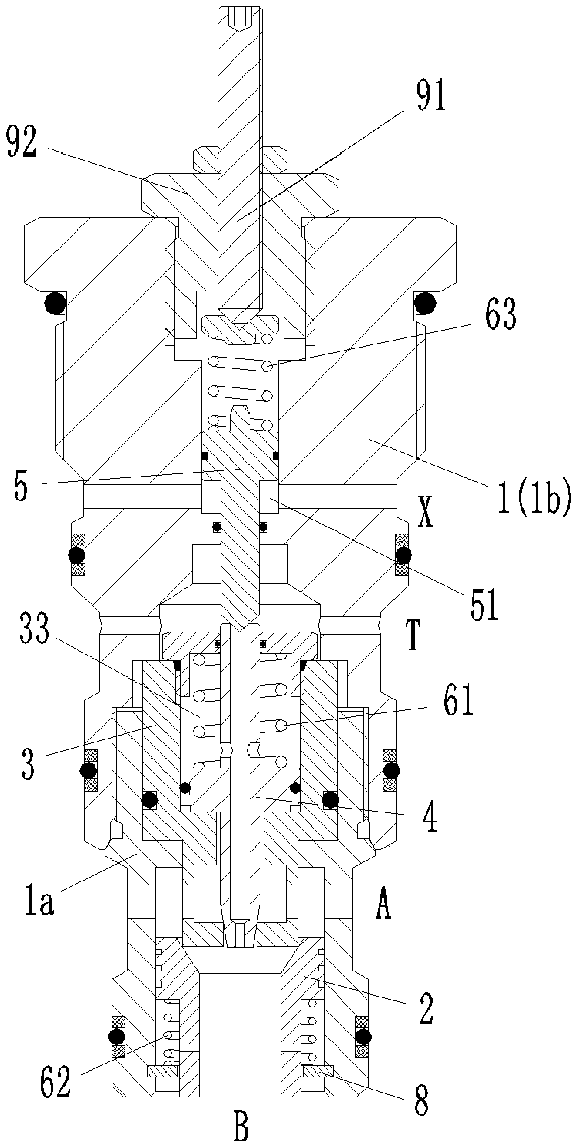
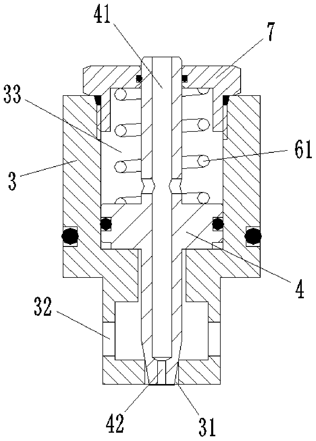
[0027] Combine figure 1 As shown, the threaded cartridge load holding valve of this embodiment includes a valve body 1, a one-way valve core 2, a valve seat 3, a flow control valve core 4, and a pilot valve core 5. Among them, the valve body 1 is a threaded cartridge valve body structure, and is provided with an oil inlet A, an oil outlet B, a control oil port X and an oil discharge port T. The one-way valve core 2, the valve seat 3, the flow control valve core 4 and the pilot valve core 5 are arranged inside the valve body 1 along the axial direction thereof.

[0028] The one-way valve core 2 is located near the oil outlet B and can move axially relative to the valve body 1. The upper end of the valve seat 3 maintains a fixed connection with the valve body 1, and the lower end forms a contact seal with the one-way valve core 2. Throu...


PUM


Abstract

The invention belongs to the technical field of hydraulic elements and discloses a thread plug-in mounting type load holding valve. A valve body is provided with an oil inlet, an oil outlet, a controloil opening and an oil unloading opening. A one-way valve element is located at the oil outlet and can move axially relative to the valve body. The lower end of a valve seat makes contact with the one-way valve element in a sealed manner. A flow control valve element is located in the valve seat and can axially move relative to the valve seat. An axial hole is formed in the lower end of the valveseat, and the lower end of the flow control valve element makes contact with the axial hole in a sealed manner. A control cavity is formed by the flow control valve element and the valve seat. A first spring is arranged in the control cavity and generates pressing force on the flow control valve element. A valve hole and a damping hole are formed in the flow control valve element, the damping hole communicates with the oil outlet and the valve hole, and the valve hole communicates with the oil unloading hole and the control cavity. The upper end of a pilot valve element forms a control oil cavity with the valve body and communicates with the control oil opening, and the lower end of the pilot valve element makes contact with the valve hole in a sealed manner. The thread plug-in mounting type load holding valve is easy to integrate and long in service life and has a safety overflow function and a micro moving function.

Description

Technical field [0001] The invention belongs to the technical field of hydraulic components, and particularly relates to a threaded cartridge type load holding valve. Background technique [0002] In the field of construction machinery and construction machinery, many equipment such as excavators, loaders, and busy excavators use cylinders to bear the load, which requires the cylinder to have a load holding function. However, the movement control of the oil cylinder mainly relies on the valve, and the valve usually has the problem of oil leakage during operation, so that when the heavy object carried by the oil cylinder is heavier, the leakage of the oil cylinder will increase, which will lead to the increase in the operation process. The load retention performance will be worse. [0003] In order to solve the problem of valve leakage that affects the load holding performance of the cylinder, the Chinese patent with application number 201510193345.8, named load holding valve, and ...

Claims


Application Information

Patent Timeline
Patent Type & Authority Applications(China)
IPC IPC(8): F15B13/01F15B13/02F16K27/00F16K15/18F16K31/36F16K17/04
CPCF15B13/015F15B13/02F15B2013/004F16K15/18F16K17/048F16K27/00F16K31/36
Inventor 武芳
Owner 江苏军源装备制造有限公司
Why Eureka
Try Eureka