
Bridge expansion joint monitoring device

A technology for monitoring devices and expansion joints, applied to measuring devices, using sound waves/ultrasonic waves/infrasonic waves to analyze solids, instruments, etc., can solve problems such as expansion of damaged parts, timely maintenance of unfavorable expansion joints, etc., to reduce interference and improve accuracy Effect

Inactive Publication Date: 2020-02-14
CHINA MERCHANTS CHONGQING COMM RES & DESIGN INST
View PDF10 Cites 4 Cited by
  • Summary
  • Abstract
  • Description
  • Claims
  • Application Information

AI Technical Summary

Problems solved by technology

[0004] The above scheme can accurately detect the displacement of the expansion joint parallel to and perpendicular to the bridge axis, but it cannot be detected when the displacement of the expansion joint parallel to and perpendicular to the bridge axis does not change and the joint part of the expansion joint is damaged , is not conducive to the timely maintenance of expansion joints, and it is easy to cause the expansion of damaged parts in the long run

Method used


Image

  • Bridge expansion joint monitoring device
  • Bridge expansion joint monitoring device

Examples


Embodiment 1

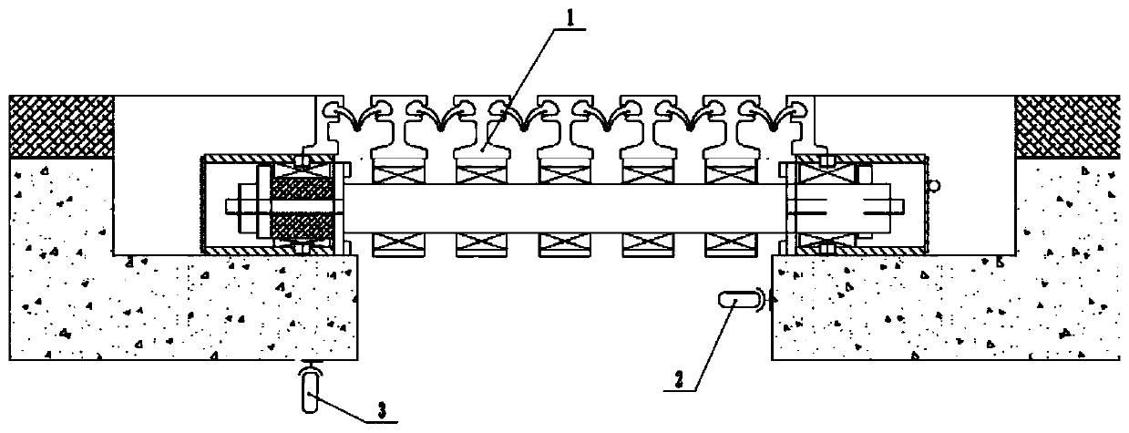
[0037] A monitoring device for bridge expansion joints includes an acquisition module and an analysis module.

[0038] Such as figure 1 As shown, the acquisition module includes a microphone, gain amplifier and analog-to-digital converter. The number of microphones is not less than two, including at least one collection microphone 2 and one noise reduction microphone 3. In this embodiment, the number of microphones is two. The acquisition microphone 2 and the noise reduction microphone 3 are both fixed under the bridge expansion joint 1 by screws. Among them, the collection microphone 2 is close to the expansion joint 1, and the noise reduction microphone 3 is far away from the expansion joint 1.

[0039] The acquisition microphone 2 and the noise reduction microphone 3 are both used to collect the sound wave signal when the vehicle passes through the expansion joint 1. The gain amplifier is connected with the acquisition microphone 2 and the noise reduction microphone 3 through ...

Embodiment 2

[0045] Such as figure 2 As shown, a bridge expansion joint monitoring device differs from the first embodiment in that it also includes a communication module, a remote processing module and a terminal module.

[0046] The communication module is signally connected with the processing unit, and the communication module is used to send the status information and the spectrum to be analyzed to the remote processing module. In this embodiment, the communication module adopts a 4G network communication module.

[0047] The remote processing module processes the status information and sends it to the terminal module. The remote processing module is one of self-built server, Alibaba Cloud server or Tencent Cloud server. In this embodiment, Tencent cloud server is used.

[0048] The terminal module is also used to send the actual failure information of the expansion joint 1 to the remote processing module, and the remote processing module matches the spectrum to be analyzed with the act...


PUM


Abstract

The invention relates to the technical field of bridge monitoring, in particular to a bridge expansion joint monitoring device. The bridge expansion joint monitoring device comprises an acquisition module and an analysis module, wherein the acquisition module is used for collecting sound wave signals when a vehicle passes through an expansion joint, and carrying out gain amplification on the soundwave signals and converting the sound wave signals into digital signals; the analysis module comprises a storage unit and a processing unit, wherein a normal state frequency spectrum is pre-stored inthe storage unit; and the processing unit draws a spectrum to be analyzed of the digital signals through a fast Fourier transform method, compares the spectrum to be analyzed with the normal state frequency spectrum, judges the state of the expansion joint, and generates state information. By adoption of the technical scheme, whether an expansion joint combining piece is damaged or not can be monitored.

Description

Technical field [0001] The invention relates to the technical field of bridge monitoring, in particular to a bridge expansion joint monitoring device. Background technique [0002] In order to meet the requirements of bridge deck deformation, bridge expansion joints are usually set between two beam ends, between beam ends and abutments, or at the hinged position of the bridge. Due to the continuous increase of traffic volume, vehicle speed, vehicle load and some minor problems left in the construction of the bridge, the damage of bridge expansion joints is very common. Generally, people cannot find out the damage of the expansion joint in time. If the damage is not obvious, it is difficult to find even if the joints of the expansion joint of the bridge are damaged. The damage of the joints of the bridge expansion joint will cause more turbulence when the vehicle is driving, noise and noise. The phenomenon of vehicle jumping is aggravated and endangers the safety and service life...

Claims


Application Information

Patent Timeline
IPC IPC(8): G01N29/04G01B17/00
CPCG01B17/00G01N29/04G01N2291/023G01N2291/0232
Inventor 郑万山刘怀林高文军唐光武
Owner CHINA MERCHANTS CHONGQING COMM RES & DESIGN INST
Learn More