
A mems attenuator testing device

A test device and attenuator technology, which is applied in the direction of measuring device, radio frequency circuit test, electronic circuit test, etc., can solve the problems of radio frequency leakage, failure to test other MEMS devices, and non-reusable parts of the test device, so as to prevent radio frequency leakage , cost reduction effect

Active Publication Date: 2021-07-09
THE 41ST INST OF CHINA ELECTRONICS TECH GRP
View PDF8 Cites 0 Cited by
  • Summary
  • Abstract
  • Description
  • Claims
  • Application Information

AI Technical Summary

Problems solved by technology

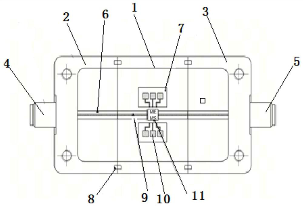
[0006] In order to solve the above problems, the present disclosure proposes a MEMS attenuator test device. In order to solve the problem that the existing MEMS device test device is usually a special test device, the present disclosure cannot test other MEMS devices, and the components of the test device cannot be reused to test MEMS devices. There is a technical problem of radio frequency leakage in radio frequency indicators

Method used


Image

  • A mems attenuator testing device
  • A mems attenuator testing device
  • A mems attenuator testing device

Examples


Embodiment Construction

[0035] The present disclosure will be further described below in conjunction with the accompanying drawings and embodiments.

[0036] It should be noted that the following detailed description is exemplary and intended to provide further explanation of the present disclosure. Unless defined otherwise, all technical and scientific terms used herein have the same meaning as commonly understood by one of ordinary skill in the art to which this disclosure belongs.

[0037] It should be noted that the terminology used herein is only for describing specific embodiments, and is not intended to limit the exemplary embodiments according to the present disclosure. As used herein, unless the context clearly dictates otherwise, the singular is intended to include the plural, and it should also be understood that when the terms "comprising" and / or "comprising" are used in this specification, they mean There are features, steps, operations, means, components and / or combinations thereof.

...


PUM


Abstract

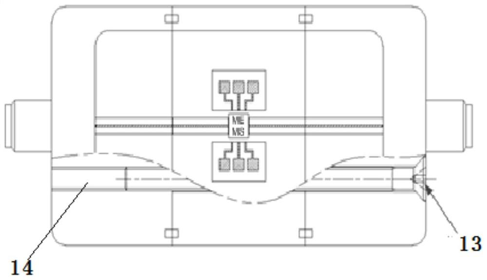
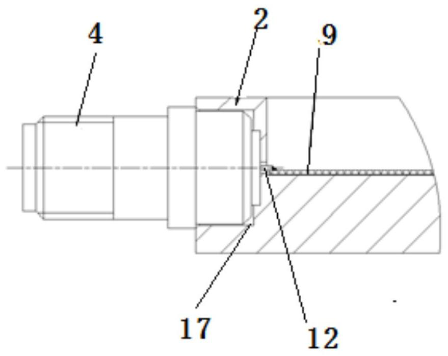
The present disclosure provides a MEMS attenuator testing device, including a first cavity, located in a second cavity and a third cavity; a connector, the connecting machine includes a first connector and a second connector, and the first connector and The second connectors respectively include inner conductors, the first connector is screwed into the first cavity, the second connector is screwed into the second cavity; the microstrip, the first microstrip is fixed on the second cavity and the second cavity On the three cavities; the second microstrip and the third microstrip are fixed on the first cavity; the third microstrip is connected to the first microstrip and the MEMS device by gold wire bonding; the first microstrip The second microstrip sheet is connected to the inner conductor; the second microstrip sheet includes several control circuit modules, the lower ends of several control circuit modules are connected to the corresponding MEMS devices to be tested through gold wire bonding, and the upper ends of several control circuit modules are connected through gold wire bonding. Corresponding control lines are respectively connected. It has versatility, can test other MEMS devices, has the advantages of reusable parts and prevents radio frequency leakage.

Description

technical field [0001] The disclosure belongs to the field of mechanical manufacturing and testing equipment, and in particular relates to a MEMS attenuator testing device. Background technique [0002] The statements in this section merely provide background information related to the present disclosure and do not necessarily constitute prior art. [0003] MEMS technology is a system that integrates microelectronics and machinery through the integration of microelectronics technology and precision machining technology. In terms of microwave, MEMS devices have the advantages of low cost, ultra-miniaturization, and easy integration with other circuits. They are an important way to realize the miniaturization of instruments and are of great significance to the development of measuring instruments and test systems. There are many indicators of MEMS devices, and different test methods and test conditions will affect the test results. [0004] In the existing testing device, tw...

Claims


Application Information

Patent Timeline
Patent Type & Authority Patents(China)
IPC IPC(8): G01R27/28G01R31/28
CPCG01R27/28G01R31/2822
Inventor 刘长春赵建波许晓龙王金龙文春华郑文峰
Owner THE 41ST INST OF CHINA ELECTRONICS TECH GRP
Learn More