A fixing device for transformer copper bars

A technology for fixing devices and transformers, which is applied in transformer/inductor components, transformer/inductor cooling, inductor/transformer/magnet manufacturing, etc., which can solve the problem of temperature rise, high temperature of copper bars, and lack of buffering of copper bars at the beginning Function and other issues, to achieve the effect of improving the stability of the connection and easy distribution

Inactive Publication Date: 2020-12-22
玉环市梓鑫机械有限公司
View PDF7 Cites 0 Cited by
  • Summary
  • Abstract
  • Description
  • Claims
  • Application Information

AI Technical Summary

Problems solved by technology

Compared with the patent CN102176370A, the fixing plate used to fix the leading copper bar is welded on the outgoing line template. Although it plays a role in fixing the leading copper bar, this fixing method is too mechanically connected. When the leading copper bar is impacted by the outside At the same time, it does not have a good buffering effect on the copper bar at the beginning, and the patent CN102176370A only fixes the fixed plate on one side of the copper bar, and its fixing stability needs to be improved; in addition, the temperature of the finished coil will increase when it is working. , so that the copper bar also has a certain high temperature phenomenon, and the fixed structure in the prior art only plays a role in fixing the copper bar, and the heat dissipation performance of the copper bar itself needs to be improved

Method used


Image

  • A fixing device for transformer copper bars
  • A fixing device for transformer copper bars
  • A fixing device for transformer copper bars

Examples


Embodiment 1

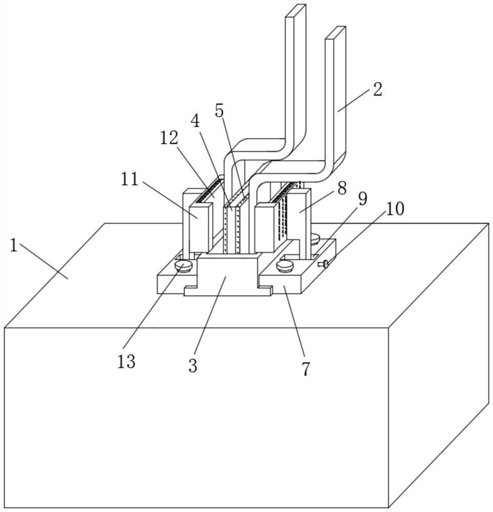
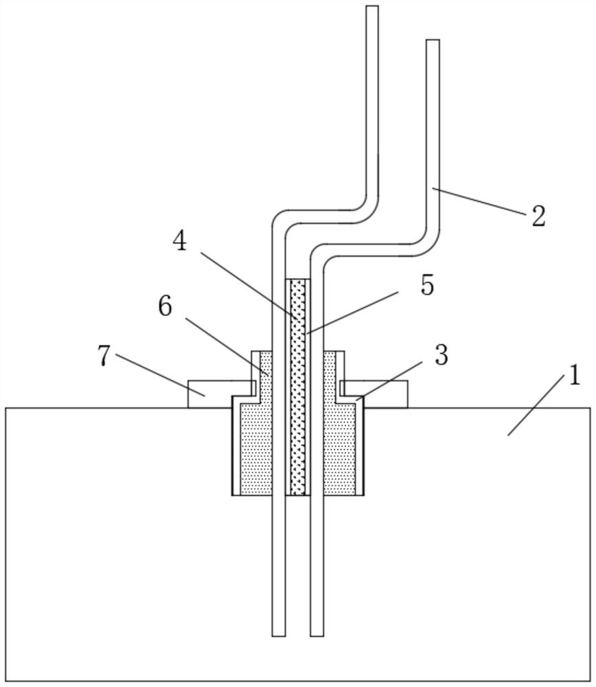
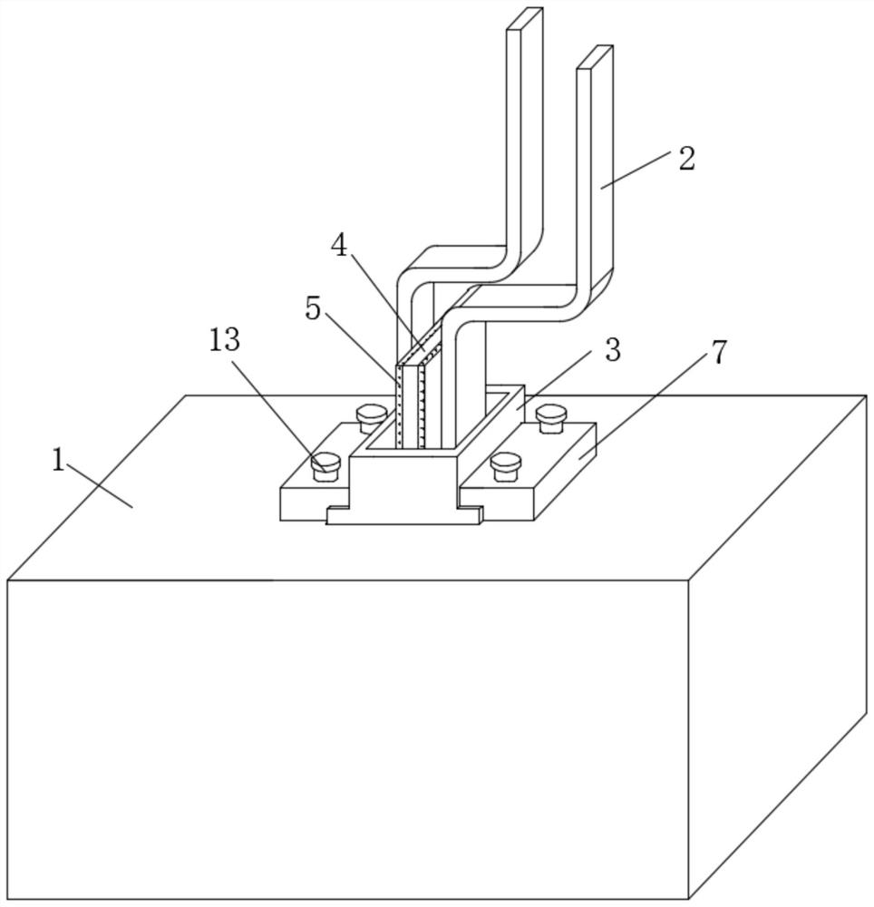
[0041] see Figure 1-Figure 2 , a fixing device for a copper bar of a transformer, including a convex mounting plate 3 for fixing two copper bar bodies 2 to an outgoing line template 1, the convex mounting plate 3 is embedded in the outgoing line template 1, and the convex mounting plate 3 is embedded in the outgoing line template 1. The interior of the mounting plate 3 is provided with a fixed cavity for fixing the copper bar body 2. The middle part of the fixed cavity is fixedly connected with an insulating partition 4, and the two copper bar bodies 2 are located on both sides of the insulating partition 4. Both sides of the plate 4 are provided with a buffer layer 5 against the inner side walls of the two copper bar bodies 2, and the cooperation of the insulating partition 4 and the convex mounting plate 3 can not only realize the limit and fixation of the two copper bar bodies 1 It also plays an insulating role between the two copper bar bodies, while the buffer layer 5 pr...


PUM


Abstract

The invention discloses a fixing device for a transformer outgoing copper bar and a fixing method thereof and belongs to the technical field of transformer outgoing copper bar fixing. The fixing device is characterized in that a convex mounting plate is matched with an insulating partition plate for use, the limiting and fixing effect on two copper bar bodies is achieved, the two copper bar bodiesare insulated, a limiting plate with a heat dissipation mechanism is installed on one side of the convex mounting plate through a fixing plate, and the fixing plate is installed on an outer side of the convex mounting plate in an embedded mode to further play a role in fixing the convex mounting plate and play a role in supporting the limiting plate with the heat dissipation mechanism. The fixingdevice is advantaged in that the horizontal position of the limiting plate is adjusted according to the thickness of the copper bar bodies, the limiting plate drives the heat dissipation mechanism toabut against outer side walls of the copper bar bodies, on one hand, the copper bar body fixing device is further suitable for fixing the copper bar bodies with different thicknesses, on the other hand, the copper bar bodies are cooled through contact connection of the heat dissipation mechanism.

Description

technical field [0001] The invention relates to the technical field of fixing copper bars of transformers, and more specifically relates to a fixing device for copper bars of transformers. Background technique [0002] In the process of resin casting dry-type transformer winding, it can be divided into two processes: winding and pouring. The filling of the internal gap of the winding realizes the mechanical strength and electrical insulation of the structure after curing. For the leading copper bars of cast-type transformers, it is easy to touch the leading copper bars during the handling and pouring process to change the position of the copper bars, which will cause the finished coils cast out to fail to meet the requirements and directly affect the quality of the transformer. [0003] After searching, the Chinese patent authorization number is CN102176370A, which discloses "A Method for Fixing the Leading Copper Bar of a Transformer", a method for fixing the leading coppe...

Claims


Application Information

Patent Timeline
Patent Type & Authority Patents(China)
IPC IPC(8): H01F27/00H01F27/22H01F27/29H01F27/32H01F41/00
CPCH01F27/00H01F27/22H01F27/29H01F27/324H01F41/00
Inventor 高伟李昌侠
Owner 玉环市梓鑫机械有限公司
Why Eureka
Try Eureka