
Movable electrical cabinet

An electrical cabinet, mobile technology, applied in electrical components, substation/distribution enclosures, substation/switch layout details, etc., can solve problems such as affecting the maintenance process and results, cluttering the interior of the electrical cabinet, and reducing the space for workers to move. To achieve the effect of facilitating subsequent maintenance, avoiding wire movement, and avoiding winding and knotting

Active Publication Date: 2020-02-21
BEIJING HCRT ELECTRICAL EQUIP
View PDF6 Cites 1 Cited by
  • Summary
  • Abstract
  • Description
  • Claims
  • Application Information

AI Technical Summary

Problems solved by technology

[0003] 1. Common electrical cabinets are basically placed on the ground, which is not easy to move and occupies a large area, which requires a large space for placement. When there are wires outside the electrical cabinet, the wires are easy to hinder the actions of the operator. At the same time The wires inside the electrical cabinet are prone to entanglement and knotting without treatment, making the inside of the electrical cabinet messy and affecting subsequent repairs and maintenance;
[0004] 2. The doors of the electrical cabinets can only be opened and closed by 90° from left to right. When workers check and repair the interior of the electrical cabinet, the opened cabinet doors usually have a certain impact on the actions of the workers, which reduces the activity space of the workers. In some cases, it will also block the workers' sight, which will affect the maintenance process and results

Method used


Image

  • Movable electrical cabinet
  • Movable electrical cabinet
  • Movable electrical cabinet

Examples


Embodiment Construction

[0026] The embodiments of the present invention will be described in detail below with reference to the accompanying drawings, but the present invention can be implemented in many different ways as defined and covered by the claims.

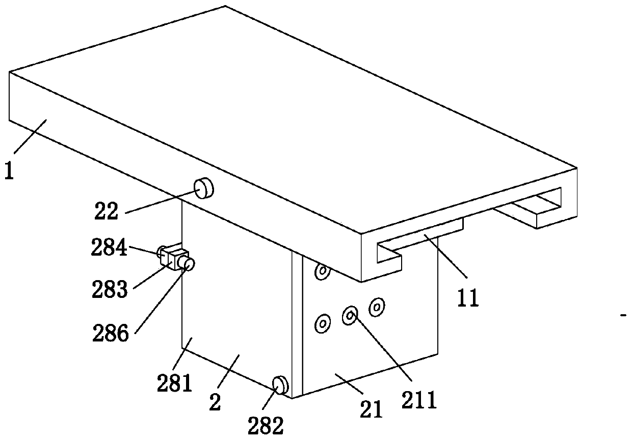
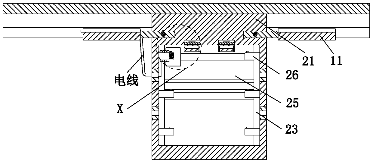
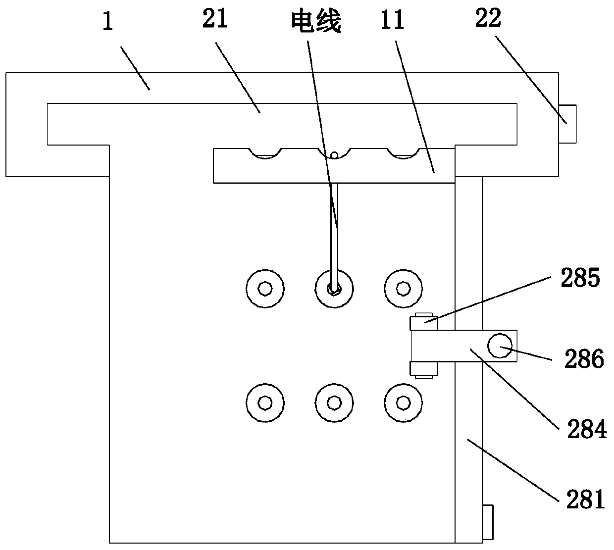
[0027] Such as Figure 1 to Figure 6 As shown, a mobile electrical cabinet includes a track plate 1 and a cabinet group 2, and the lower end of the track plate 1 is fitted with the cabinet group 2 through a sliding fit.

[0028]The cabinet group 2 includes a cabinet body 21, positioning screws 22, slideway plates 23, clamping columns 24, telescopic slide bars 25, side winding columns 26, U-shaped rotating plates 27 and upper winding columns 28, the upper end of the cabinet body 21 The lower end of the track plate 1 is in a sliding fit, and the front end of the cabinet body 21 is fitted with a set screw 22 through thread fit. The set screw 22 and the front end of the track plate 1 are thread fit. The rear end of the rear end is symmetrically equi...


PUM


Abstract

The invention relates to a mobile electrical cabinet. The cabinet comprises a track plate and a cabinet group. The cabinet group is mounted at the lower end of the track plate in a sliding fit manner.The invention relates to the mobile electrical cabinet. According to the invention, the electrical cabinet is used based on the design concept of mobile multi-stage wire arrangement; the electrical cabinet can be installed on the top of a wall, and the mounting position of the electrical cabinet on the top of the wall can be determined as required; the mobile electrical cabinet occupies a small area, which saves ground space; the whole placing space is tidy and clear; a wire arrangement board provided by the invention can arrange wires outside the electrical cabinet; the wires can be horizontally routed along the top of the mounting wall, which avoids disorder with other wires and a phenomenon of hanging falling, and facilitates subsequent maintenance; and concave arc grooves in the wirearrangement board can play a role in limiting and fixing the wires placed thereon, so as to prevent movement of the wires.

Description

technical field [0001] The invention relates to the technical field of electrical cabinet equipment, in particular to a mobile electrical cabinet. Background technique [0002] The electrical cabinet is made of steel and used to protect the normal operation of the components, also known as the power distribution cabinet. The electrical cabinet has two main functions: one is to distribute and control the electrical equipment, and the other is to control the power consumption of the circuit. Provide power-off protection in case of overload, short circuit and leakage. The common types include fixed panel type, drawer type, protective type, and dynamic lighting type. The electrical cabinet is widely used in chemical industry, environmental protection industry, power system, metallurgical system, In industry, nuclear power industry, fire safety monitoring, transportation industry, etc., the materials for making electrical cabinets are generally divided into two types: hot-rolled ...

Claims


Application Information

Patent Timeline
Patent Type & Authority Applications(China)
IPC IPC(8): H02B1/30H02B1/20H02B1/32E05C19/00
CPCE05C19/00H02B1/20H02B1/30H02B1/32
Inventor 王斌斌金严
Owner BEIJING HCRT ELECTRICAL EQUIP
Learn More