A switchgear with high heat dissipation efficiency

A switchgear, high heat dissipation technology, applied in substation/switch layout details, substation/switchgear cooling/ventilation, electrical components, etc. and other problems, to achieve the effect of simple structure, sufficient heat dissipation and good heat dissipation effect

Active Publication Date: 2021-06-01
海南电网有限责任公司琼海供电局
View PDF5 Cites 0 Cited by
  • Summary
  • Abstract
  • Description
  • Claims
  • Application Information

AI Technical Summary

Problems solved by technology

[0003] The switchgear generates a lot of heat when it is working, which causes the ambient temperature in the switchgear to increase. Affected by the ambient temperature, the working performance of the components in the switchgear is reduced, which is prone to safety accidents, and working at high temperature for a long time will reduce the service life of the switchgear. , the traditional switch cabinet generally has cooling holes on the cabinet body, and cooling fans are installed in the switch cabinet, but this type of cooling method cannot fully dissipate heat, and the cooling effect is poor

Method used


Image

  • A switchgear with high heat dissipation efficiency
  • A switchgear with high heat dissipation efficiency
  • A switchgear with high heat dissipation efficiency

Examples


Embodiment 1

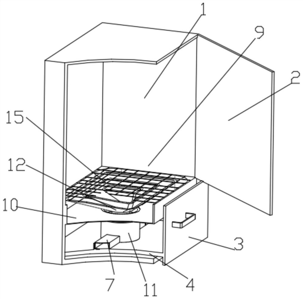
[0024] see Figure 1 to Figure 4 A switchgear with high heat dissipation efficiency provided by the present invention includes a box body 1 and a cyclone cooling device 9, the side of the box body 1 is hinged with a box door 2, and the bottom of the box body 1 is slidably connected with a The fixed plate 4 can be pulled out of the lighting cabinet; the fixed plate 4 is connected with a cover plate 3 matching the box body 1, and the fixed plate 4 is provided with a first ventilation duct 5, the The bottom of the first ventilation duct 5 is communicated with an air guide pipe 6, and the box body 1 is provided with an air inlet pipe 7 that communicates with the air guide pipe 6, and the inside of the first ventilation duct 5 is connected with a ventilation fan 8 , when the ventilation fan 8 breaks down or accumulates dust, the fixing plate 4 can be pulled out of the switch cabinet to facilitate the maintenance of the ventilation fan 8 and to remove the dust accumulated on the ven...

Embodiment 2

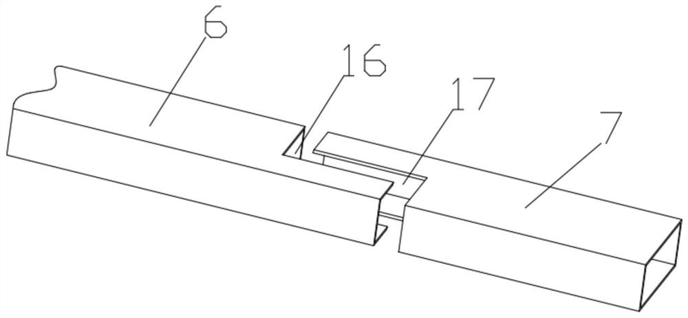
[0028] see image 3 , The difference between this embodiment and Embodiment 1 is that the cross section of the air guide pipe 6 is a rectangular air guide pipe 6 , and the cross section of the air inlet pipe 7 is a rectangular air inlet pipe 7 . It is convenient for the air guide pipe 6 to communicate with the air inlet pipe 7 when it is pulled back and forth in the switch cabinet.

[0029] Specifically, the air inlet pipe 7 located in the box body 1 is provided with a first notch 16, and the free end of the air guide pipe 6 is provided with a second notch 17, and the first notch 16 is connected with the first notch. The two notches 17 are provided with mutually matching chamfers. When the fixed plate 4 is pushed into the light opening cabinet and the air guide tube 6 communicates with the air inlet tube 7, the airtightness of the air guide tube 6 communicating with the air inlet tube 7 is improved.

Embodiment 3

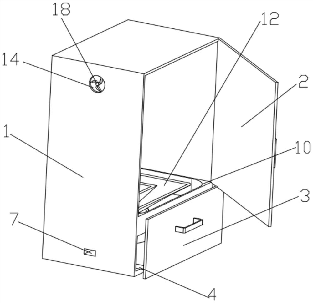
[0031] see Figure 2 to Figure 5 , The difference between this embodiment and Embodiment 1 is that a cooling fan 18 is provided in the vent. Effectively dissipate the hot air in the switch cabinet out of the switch cabinet.

[0032] Specifically, the cooling fan 18 is connected to the air outlet 14 through a first anti-vibration device (not shown). Reduce the degree of vibration of the switch cabinet when the cooling fan 18 is working.

[0033] Specifically, the ventilation fan 8 is connected to the first ventilation duct 5 through the second anti-vibration device 19 . Reduce the degree of vibration of the switch cabinet when the ventilation fan 8 is working.

[0034] Specifically, the first anti-vibration device (not marked) and the second anti-vibration device 19 both include a cross-shaped telescopic rod 20 and a spring 20, and the cooling fan 18 is connected to the air outlet through the corresponding cross-shaped telescopic rod 20 14 , the ventilation fan 8 is connect...


PUM


Abstract

The invention provides a switchgear with high heat dissipation efficiency, which includes a box body and a cyclone cooling device, the side of the box body is hinged with a box door, the bottom of the box body is slidably connected with a fixed plate, and the fixed plate is connected with a box matching the box body. The cover plate, the fixed plate is provided with a first ventilation pipe, the bottom of the first ventilation pipe is connected with an air guide pipe, the box body is provided with an air inlet pipe connected with the air guide pipe, and the inside of the first ventilation pipe is connected with a ventilation pipe. The fan and the cyclone cooling device are fixed above the first ventilation duct. The cyclone cooling device includes an outer cylinder, a second ventilation duct and an air guide tube. The air guide tube is arranged inside the outer cylinder, and the second ventilation duct communicates with the outer tube. , The outer cylinder, the second ventilation duct and the air guide tube are provided with cavities, the cavities are equipped with cooling liquid, and the box body is provided with a number of air outlets. The invention can evenly disperse and blow the wind blown by the ventilation fan to the cabinet through the cyclone cooling device, so as to realize sufficient heat dissipation of the switch cabinet, and the temperature decreases when the wind passes through the cyclone cooling device, so as to achieve a good heat dissipation effect.

Description

technical field [0001] The invention relates to the technical field of heat dissipation of switch cabinets, in particular to a switch cabinet with high heat dissipation efficiency. Background technique [0002] The main function of the switch cabinet is to open and close, control and protect the electrical equipment during the process of power generation, transmission, distribution and power conversion in the power system, so the normal operation of the switch cabinet is very important. [0003] The switchgear generates a lot of heat when it is working, which causes the ambient temperature in the switchgear to increase. Affected by the ambient temperature, the working performance of the components in the switchgear is reduced, which is prone to safety accidents, and working at high temperature for a long time will reduce the service life of the switchgear. , Traditional switch cabinets generally have cooling holes on the cabinet body, and cooling fans are installed in the sw...

Claims


Application Information

Patent Timeline
Patent Type & Authority Patents(China)
IPC IPC(8): H02B1/56H02B1/30
CPCH02B1/30H02B1/565
Inventor 黄雄吴天杰林少佳黄日瑞岑琼霞庞小莉张国刚
Owner 海南电网有限责任公司琼海供电局
Why Eureka
Try Eureka