
Differential pressure sensor filter and use thereof

A filter and sensor technology, applied in the field of differential pressure sensor filters, can solve problems such as room pressure out of control, filter clogging, inaccurate detection of differential pressure sensors, etc., and achieve the effect of improving the filtering effect

Inactive Publication Date: 2020-02-18
HARBIN VETERINARY RES INST CHINESE ACADEMY OF AGRI SCI
View PDF7 Cites 3 Cited by
  • Summary
  • Abstract
  • Description
  • Claims
  • Application Information

AI Technical Summary

Problems solved by technology

[0005] The present disclosure provides a differential pressure sensor filter and its application to at least partly solve the following technical problems: the current filter connected at the differential pressure sensor interface is simple in design, and does not consider the corresponding large amount of water vapor and humidity during spraying The problem of filter clogging caused by the environment, which will further lead to inaccurate detection of differential pressure sensor, which will lead to loss of control of room pressure

Method used


Image

  • Differential pressure sensor filter and use thereof
  • Differential pressure sensor filter and use thereof
  • Differential pressure sensor filter and use thereof

Examples


no. 1 example

[0040] In a first exemplary embodiment of the present disclosure, a differential pressure sensor filter is provided.

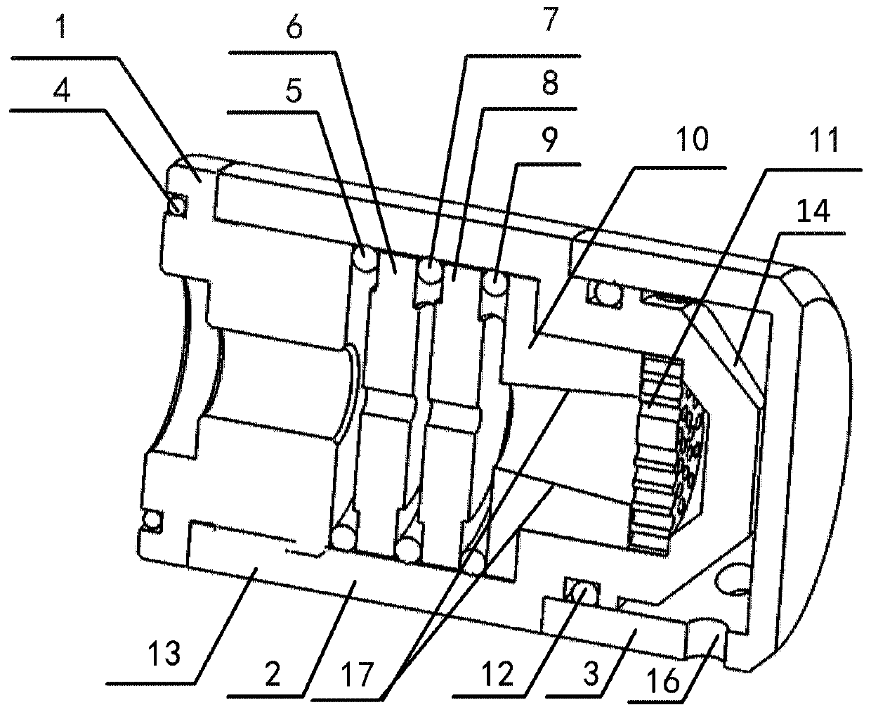
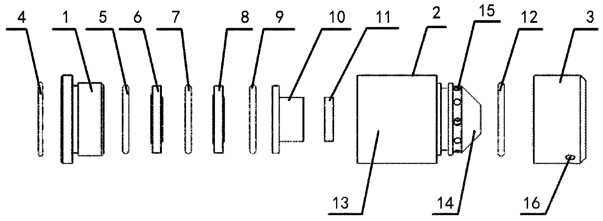
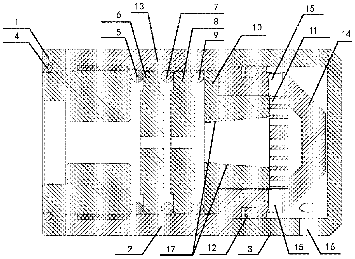
[0041] figure 1 It is a three-dimensional structural schematic diagram of a differential pressure sensor filter according to an embodiment of the present disclosure. figure 2 For such figure 1 An exploded view of the structure of the differential pressure sensor filter shown. image 3 For such figure 1 Cutaway view of differential pressure sensor filter shown.

[0042] Among them, in the description of the full text, "top" is along the figure 2 / image 3 In the right direction, "bottom" is along the figure 2 / image 3 Orientation on the left side. The description of the top and bottom is relative to the drawings. In the actual structure, when the position of the overall structure is shifted or reversed, the corresponding description direction may change.

[0043] refer to Figure 1-Figure 3As shown, the differential pressure sensor filter of the...

no. 2 example

[0063] In a second exemplary embodiment of the present disclosure, an application of the differential pressure sensor filter in a biosafety laboratory, especially in a chemical shower room of a biosafety laboratory is provided. Of course, it can also be applied to isolate the pressure port of the differential pressure sensor in other humid environments. In addition, it is also suitable for application scenarios that prevent the leakage of aerosols such as viruses and bacteria.

[0064] In the chemical shower room, based on the connection between the differential pressure sensor interface inside the differential pressure sensor filter and the differential pressure sensor, when the differential pressure test is performed, due to the setting of the water retaining cover and the water vapor condensation net, the water vapor is blocked and large Part of the water vapor is effectively exported. After filtering, the gas that enters the connecting pipe of the differential pressure sen...


PUM


Abstract

Provided are a differential pressure sensor filter and use thereof. The pressure difference sensor filter comprises an upper cover, a base, and a water stopping cover; water-draining gas vents are formed in the top of the upper cover, and a water vapor condensation net is arranged on the inner side of the top; the base is connected with the bottom of the upper cover, and a differential pressure sensor interface is connected inside the base; the water stopping cover covers the top of the upper cover, and gas vents are formed in the surface of the water stopping cover. Most of the water vapor isstopped by the water stopping cover during spraying, and only a small portion of the water vapor enters the filter via the gas vents of the water stopping cover; vaporized water molecules in the water vapor are condensed and dried by the water vapor condensation net; the condensed water flows out via the water-draining gas vents and is discharged to the outside of the filter via the gas vents inthe water stopping cover; water stopping and draining functions are achieved on the basis of ensuring the smoothness of the gas path; and the technical problem of failure in pressure sensing detectionor inaccurate detection result due to blockage of the differential pressure sensor resulting from admission of large quantity of water vapor into the sensor is effectively solved.

Description

technical field [0001] The disclosure belongs to the technical field of biological safety laboratory equipment, and relates to a differential pressure sensor filter and its application. Background technique [0002] A biosafety laboratory is a biological laboratory or animal laboratory that can avoid or control the hazards of harmful biological factors being manipulated and meet the requirements of biosafety through protective barriers and management measures. [0003] The chemical shower room is an important barrier to isolate the laboratory from the clean area. Laboratory operators wear positive pressure protective clothing to spray chemicals in the chemical shower room, rinse and disinfect the surface of the protective clothing, and avoid contamination when the experimenter leaves. Take the biohazardous factors out of the contaminated area when in the area. As an important part of the biosafety laboratory, the chemical shower room also needs to monitor and control the pr...

Claims


Application Information

Patent Timeline
Patent Type & Authority Applications(China)
IPC IPC(8): B01D46/12B01D46/44B01D46/00
CPCB01D46/0002B01D46/0012B01D46/12B01D46/446B01D46/62
Inventor 王栋佟海龙卜云婷张珂智魏一赵春晖孙百明吕士昆
Owner HARBIN VETERINARY RES INST CHINESE ACADEMY OF AGRI SCI
Learn More