Steel plate punching device capable of automatically replacing punch

An automatic replacement and punching device technology, applied in the field of stamping machinery, can solve the problems of high stamping cost, time-consuming and labor-intensive, and delayed production time

Pending Publication Date: 2020-02-18
义乌市创伟电器机械有限公司
View PDF0 Cites 9 Cited by
  • Summary
  • Abstract
  • Description
  • Claims
  • Application Information

AI Technical Summary

Problems solved by technology

[0003] The current stamping equipment is complex and diverse, with complete functions and a high degree of automation. When the plate is stamped, different holes need to be opened on the surface of the plate. At this time, different punches are required for stamping. The traditional method is to use an assembly line for stamping. , requires repeated positioning and installation, and the punching operation of the plate cannot be completed in one installation. The punching process is complicated and the punching cost is high. At the same time, the traditional punching equipment needs to manually replace the punching head. Replacing the punching head is time-consuming and labor-intensive, which delays the production time and affects the production efficiency. Therefore, a mechanical device that can automatically replace the punching head and complete the plate punching with one installation is needed to solve the above problems.

Method used


Image

  • Steel plate punching device capable of automatically replacing punch
  • Steel plate punching device capable of automatically replacing punch
  • Steel plate punching device capable of automatically replacing punch

Examples


Embodiment 1

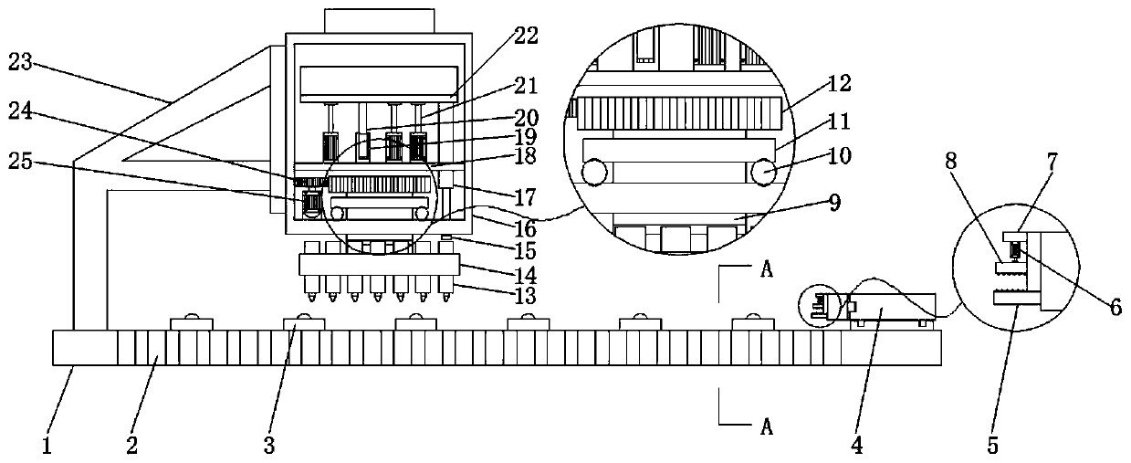
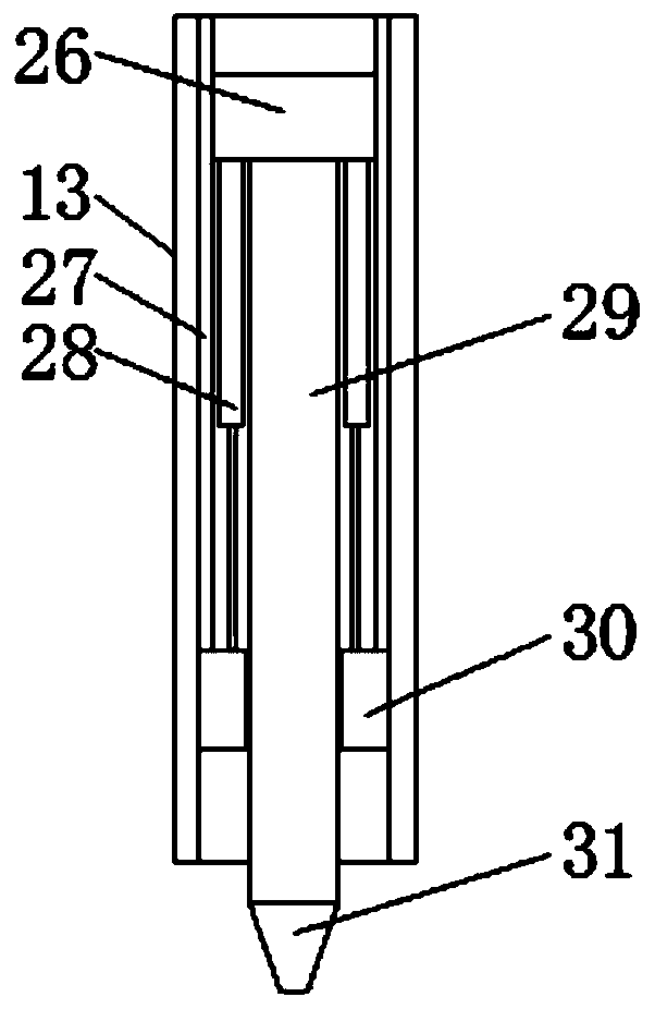
[0028] Embodiment one, with reference to figure 1 , image 3 with Figure 4 , a steel plate punching device that automatically replaces the punch, including a mounting table 1 and a casing 16, one end of the top surface of the mounting table 1 is fixedly installed with the organic casing 16 through a bracket 23, and the bottom surface of the casing 16 is connected with a rotating shaft 9 for rotation. , and the bottom surface of the rotating shaft 9 is welded with a turntable 14, the turntable 14 is a disc-shaped structure, the surface of the turntable 14 is fixedly connected with a sleeve 13, and the inside of the sleeve 13 is welded with a track 27, and the inside of the sleeve 13 is slidably connected with a slider 26. The slider 26 is slidingly connected with the track 27. The track 27 provides a guide for the slider 26 to prevent the slider 26 from shaking, and the bottom surface of the slider 26 is connected with a punch 31 through a punch rod 29, wherein the sleeve 13 ...

Embodiment 2

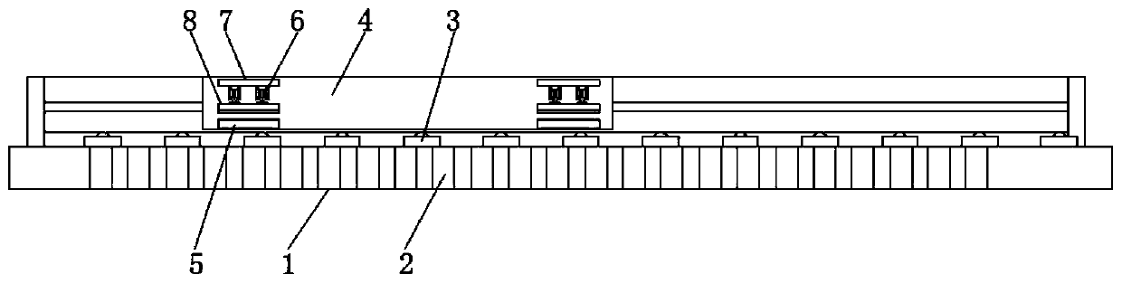
[0029] Embodiment two, refer to figure 2 , Figure 5 with Image 6, the other end of the top surface of the installation table 1 is installed with a biaxial slide 4, and the bottom surface of the side wall of the sliding end of the biaxial slide 4 is fixedly installed with a bottom splint 5, and the top surface of the side wall of the biaxial slide 4 corresponds to the bottom splint 5 position is welded with fixed plate 7, the bottom surface of fixed plate 7 is connected with upper splint 8 through hydraulic cylinder 6, two upper splint 8 and bottom splint 5 are provided, which is convenient for stably clamping the steel plate, and the top surface of installation platform 1 is fixedly connected with ball support Seat 3, wherein the ball support seat 3 includes a ball seat 301 and a first ball 302, and the first ball 302 is located inside the ball seat 301 and is rollingly connected with the ball seat 301, the top surface of the first ball 302 and the top surface of the botto...

Embodiment 3

[0030] Embodiment three, refer to figure 1 , the bottom surface of the top plate 22 is located between the cylinders 21 and is fixedly connected with a slide bar 20, the top surface of the mounting plate 18 is fixedly installed with a guide sleeve 19 corresponding to the position of the slide bar 20, the slide bar 20 is inserted into the guide sleeve 19 and is slidably connected with the guide sleeve 19, The slide bar 20 vertically moves up and down along the guide sleeve 19 to provide guidance for the top plate 22 and prevent the top plate 22 from shaking.


PUM


Abstract

The invention discloses a steel plate punching device capable of automatically replacing a punch. The device comprises a mounting table and a shell. In the device, a rotating shaft, a rotating plate,a sleeve and an ejector rod are utilized, when the punch needs to be replaced, a servo motor drives a driving gear to rotate for a certain number of turns, the driving gear drives a driven gear to rotate for a certain number of turns, and the driven gear drives the rotating shaft to rotate for a certain number of turns, so that the sleeve with different punches is moved to the portion under the ejector rod, a cylinder shrinks, an ejector plate is driven to move downwards quickly, then the ejector rod is driven to move downwards quickly, then a push head is driven to push a sliding block to move downwards, the sliding block moves downwards to drive a guide rod to contract, a punch rod drives the punch to punch a steel plate, a worker controls the rotation angle of the servo motor through aPLC, and then the sleeve with different punches can be switched and rotated to the portion under the push head during work for automatically switching the punches and complete punching. The automationdegree is high, the device is convenient to use, and the punching efficiency is greatly improved.

Description

technical field [0001] The invention relates to the technical field of stamping machinery, in particular to a steel plate punching device for automatically replacing punches. Background technique [0002] Stamping is to rely on presses and molds to apply external force to plates, strips, pipes and profiles, etc., to cause plastic deformation or separation, so as to obtain workpieces (stamping parts) of required shape and size. Stamping and forging belong to Plastic processing (or pressure processing), collectively known as forging, stamping blanks are mainly hot-rolled and cold-rolled steel plates and steel strips, 60-70% of the world's steel products are plates, most of which are made by stamping Finished products, automobile body, chassis, fuel tank, radiator, boiler steam drum, container casing, motor, electrical iron core silicon steel sheet, etc. are all stamped. Instruments, household appliances, bicycles, office machinery, There are also a large number of stamping pa...

Claims


Application Information

Patent Timeline
Patent Type & Authority Applications(China)
IPC IPC(8): B21D28/26B21D28/36B21D37/06B21D43/00B21D43/11
CPCB21D28/26B21D28/36B21D37/06B21D43/003B21D43/11
Inventor 朱槐钟王起任大龙
Owner 义乌市创伟电器机械有限公司
Why Eureka
Try Eureka