
Novel stamping rod structure of coal compression machine

A technology of punching rods and coal presses, which is applied in the direction of material forming presses, punching machines, presses, etc., can solve problems such as wasting time and processing efficiency, shortening the service life of punching rods, and waste of coal materials, and achieve reduction Time and cost, guaranteed processing efficiency, and increased service life

Inactive Publication Date: 2020-02-18
江门健维自动化设备有限公司
View PDF0 Cites 1 Cited by
  • Summary
  • Abstract
  • Description
  • Claims
  • Application Information

AI Technical Summary

Problems solved by technology

[0003] In the process of pressing coal briquettes with a coal press, it is often necessary to stamp the briquettes to punch the coal material out of the mold to form briquettes. However, the height of the commonly used stamping rods cannot be adjusted in modern times, and cannot be controlled during the stamping process. The force of stamping will cause the coal material to be crushed due to excessive stamping force, resulting in failure of pressing, or unable to form because of too small stamping force, which not only wastes time and processing efficiency, but also wastes coal material and cost. Excessive punching force will break or bend the punching rod, shorten the service life of the punching rod, and waste the processing cost to a certain extent. A new type of punching rod structure for coal presses is now introduced

Method used


Image

  • Novel stamping rod structure of coal compression machine
  • Novel stamping rod structure of coal compression machine
  • Novel stamping rod structure of coal compression machine

Examples


Embodiment Construction

[0023] The following will clearly and completely describe the technical solutions in the embodiments of the present invention with reference to the accompanying drawings in the embodiments of the present invention. Obviously, the described embodiments are only some, not all, embodiments of the present invention. Based on the embodiments of the present invention, all other embodiments obtained by persons of ordinary skill in the art without making creative efforts belong to the protection scope of the present invention.

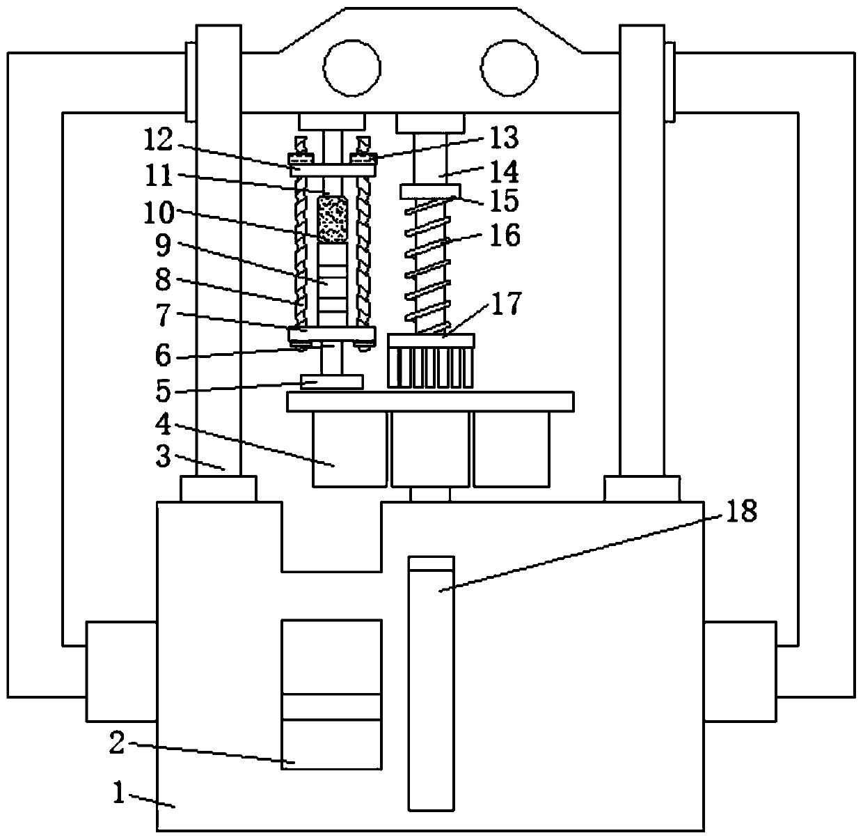
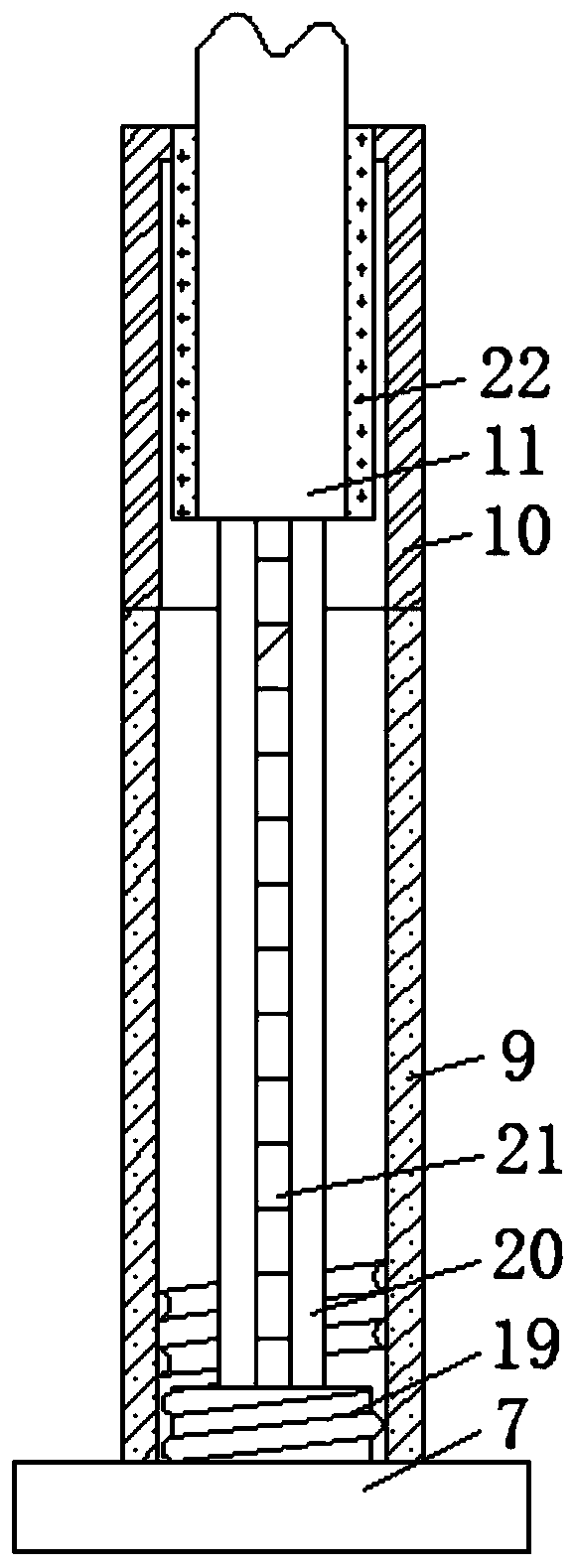
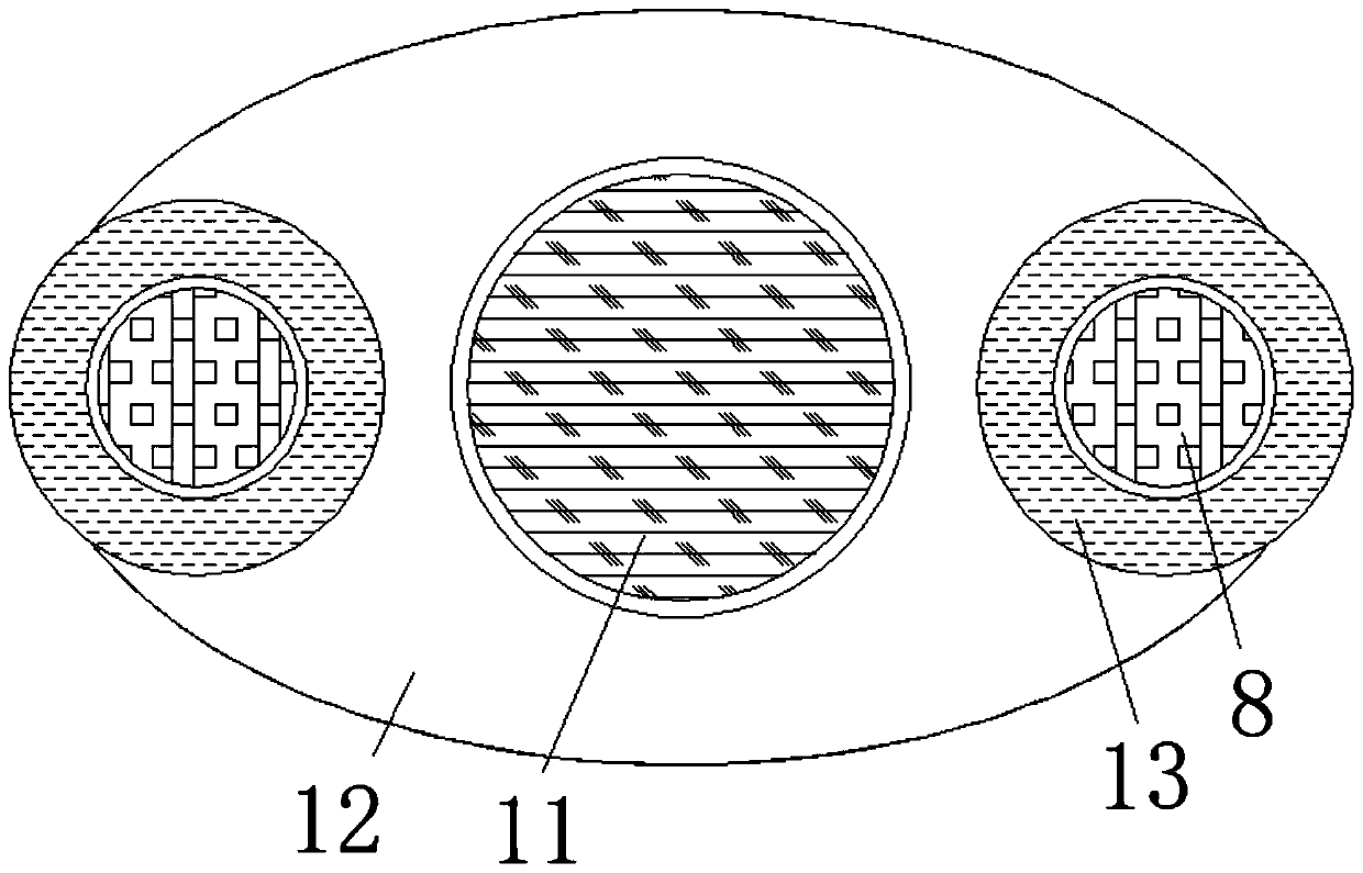
[0024] see Figure 1-4, a new type of coal press stamping rod structure, including a body 1, the two sides of the top surface of the body 1 are fixedly connected with brackets 3, the middle part of the front of the body 1 is provided with a slag outlet 18, and the front of the body 1 is located at the slag outlet 18 The left side of the body is provided with a discharge port 2, the top surface of the body 1 is movably connected with a mold 4 above the slag dis...


PUM


Abstract

The invention relates to the technical field of mechanical equipment and discloses a novel stamping rod structure of a coal compression machine. The structure comprises a machine body, wherein supports are fixedly connected to two sides of the top face of the machine body; a cinder outlet is formed in the middle of the front face of the machine body; a discharge hole is formed in the front face ofthe machine body and is located on the left side of the cinder outlet; and a mold is movably connected to the top face of the machine body and is located above the cinder outlet. The novel stamping rod structure disclosed by the invention has the beneficial effects that through adjustment of the height of a stamping rod and interactions between a screw rod and a screw, a baseplate can be driven by the screw rod to move up and down, and a stamping head is driven by the baseplate to move up and down, so the height is adjusted; problems that the height of a conventional stamping rod cannot be adjusted, acting force of stamping cannot be controlled during stamping and thus coal is crushed due to high stamping force and compression fails, or shaping cannot be realized when the stamping force is too small can be solved; and processing efficiency and quality of coal briquettes are ensured.

Description

technical field [0001] The invention relates to the technical field of mechanical equipment, in particular to a novel punching rod structure of a coal press. Background technique [0002] The briquette machine is commonly known as the honeycomb briquetting machine or the briquette machine. The briquette machine uses the processed coal as the raw material to form a certain shape of briquette by stirring and stamping. 250 briquettes of different sizes and specifications. In addition, the briquette machine can greatly expand the functions of briquettes by changing molds of different shapes, such as cylindrical and square briquettes, making this briquette machine an ideal briquette for entrepreneurs. As a machine product, the briquette machine has a simple structure and is divided into five parts: the body, rotation, feeding, stamping, and conveying. The various parts cooperate with each other and the operation is coordinated and stable. Therefore, the briquette machine has beco...

Claims


Application Information

Patent Timeline
IPC IPC(8): B30B11/10B30B1/18B30B15/00B30B15/02
CPCB30B1/18B30B11/10B30B15/00B30B15/02
Inventor 卢育兵
Owner 江门健维自动化设备有限公司
Learn More