High-density optical fiber adaptor module

A high-density, transfer technology, applied in the direction of light guides, optics, optical components, etc., can solve the problems of poor practicability, inconvenient quick disassembly and maintenance of transfer blocks, inconvenient installation and fixing of optical fibers, etc.

Inactive Publication Date: 2020-02-18
湖南彗驰科技有限公司
View PDF4 Cites 4 Cited by
  • Summary
  • Abstract
  • Description
  • Claims
  • Application Information

AI Technical Summary

Problems solved by technology

However, the above-mentioned technical solution is inconvenient to quickly disassemble and maintain the adapter block in actual use, and it is inconvenient to install and fix the optical fiber. The operation is cumbersome and the practicability is not strong.

Method used


Image

  • High-density optical fiber adaptor module
  • High-density optical fiber adaptor module
  • High-density optical fiber adaptor module

Examples


Embodiment 1

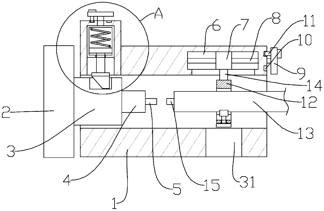
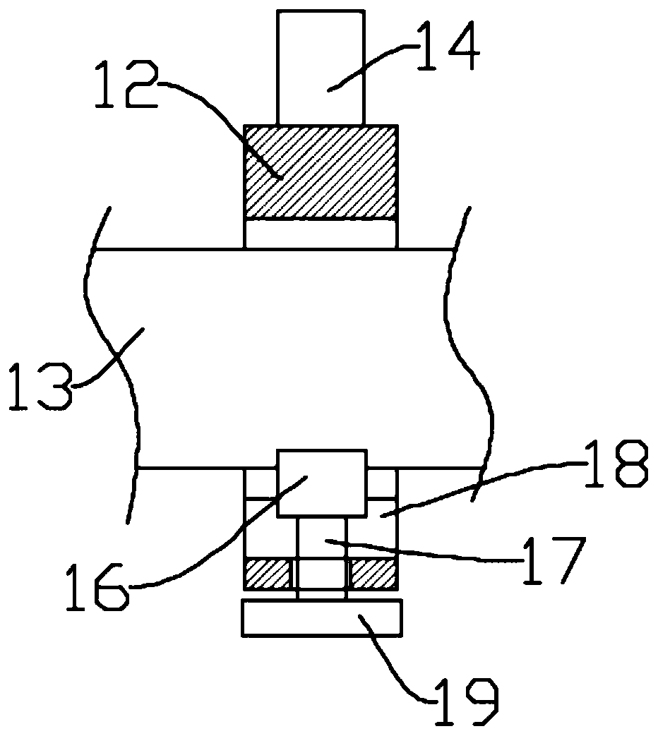
[0024] Such as figure 1 As shown, in the embodiment provided by the present invention, a high-density optical fiber transition module includes an adapter barrel 1 with both ends open, and an open end of the adapter barrel 1 is detachably installed with Connector 2, the opening of the other end of the adapter barrel 1 is detachably installed with an optical fiber 13 through a clamping assembly, and the optical fiber 13 is wrapped around the outer ring of the fiber core 15; and the other end of the adapter barrel 1 An adjustment assembly for pushing the optical fiber 13 to move towards the connector 2 is also provided.

[0025] Specifically, in the embodiment provided by the present invention, one side of the connector 2 has a connecting column 3 extending into the adapter barrel 1, and the connecting column 3 is fixedly installed with a protective cover covering the outer ring of the ferrule 5. layer 4; an installation assembly for locking and fixing the connecting column 3 is...

Embodiment 2

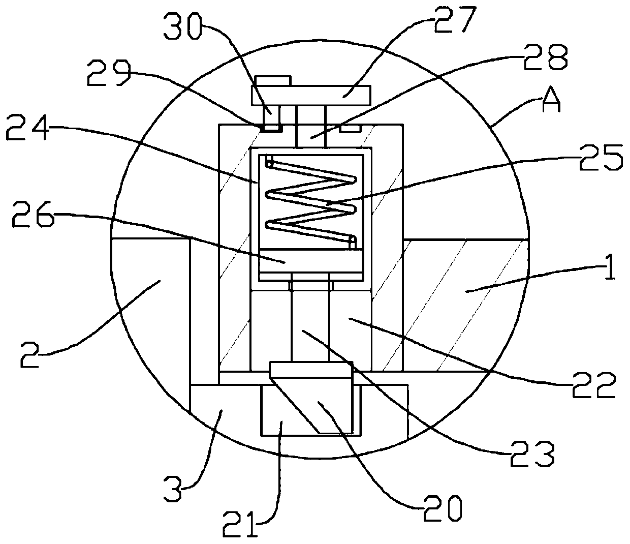
[0031] Such as figure 1 with image 3As shown, the difference from Embodiment 1 is that in the embodiment provided by the present invention, the connecting column 3 is provided with a mounting groove 21, and the mounting assembly includes a mounting block 20 that is adapted to the mounting groove 21 , the opening of the end of the adapter tube 1 is provided with a receiving groove 22, and an elastic support member is provided in the receiving groove 22 to elastically support the installation block 20, and the installation block 20 has an inclined surface The edge block structure;

[0032] Specifically, in the embodiment provided by the present invention, an operation part for adjusting the orientation of the inclined surface of the installation block 20 is also provided on the open end wall of the adapter tube 1; The elastic support member is fixedly connected to the operating shaft 28, the other end of the operating shaft 28 is fixedly mounted with the second operating disc...


PUM


Abstract

The invention, which relates to the field of communication equipment, particularly discloses a high-density optical fiber adaptor module comprising an adaptor cylinder with two open ends; a connectoris detachably mounted at the opening at one end of the adaptor cylinder; and an optical fiber is installed at the opening at the other end of the adaptor cylinder detachably by a clamping assembly andwraps the outer ring of a fiber core. Besides, an adjusting assembly for pushing the optical fiber to move towards the connector is also arranged at the other end of the adaptor cylinder. A connecting column extending into the adaptor cylinder is arranged at one side of the connector; and a protection layer coating the outer ring of an insertion core is fixedly installed on the connecting column.A mounting assembly for locking and fixing the connecting column is installed at the opening of the end portion of the adaptor cylinder. According to the embodiment of the invention, the adjusting assembly pushes the optical fiber on the clamping assembly to move towards the connector until the fiber core on the optical fiber is in butt joint with the insertion core, thereby realizing the adaptoreffect. With the mounting assembly, the dismounting, mounting, and maintenance of the adaptor block become convenient; and the operation becomes convenient.

Description

technical field [0001] The invention relates to the field of communication equipment, in particular to a high-density optical fiber transfer module. Background technique [0002] A Chinese patent with the authorized announcement number CN 207895118U discloses a fiber optic connector adapter. Passing through the ring, the optical fiber touches the ring and pulls the ring to move to the left, driving the first rope to pull the runner to rotate, so that the second rope drives the two sliders to move towards the fiber at the same time, thereby fixing the fiber, and the first rope drives the runner Rotate to make the cam rotate and lock the optical fiber, reinforce the optical fiber again, and prevent the optical fiber from loosening. Contact with the fiber core to achieve the effect of transfer. However, the above-mentioned technical solution is not convenient for quick disassembly and maintenance of the adapter block during actual use, and it is inconvenient for the installat...

Claims


Application Information

Patent Timeline
Patent Type & Authority Applications(China)
IPC IPC(8): G02B6/38
CPCG02B6/381G02B6/3858
Inventor 吴何生王芳
Owner 湖南彗驰科技有限公司
Why Eureka
Try Eureka