Welding tool for pump valve mounting and welding method thereof

A technology for welding tooling and installation, which is applied in the field of welding tooling for pump and valve installation, which can solve the problems of operator influence, toxic smoke, smoke and dust cannot be completely absorbed, etc., and achieve the effect of simplifying welding steps and facilitating welding operations

Active Publication Date: 2020-02-21
合肥华升泵阀股份有限公司
View PDF15 Cites 0 Cited by
  • Summary
  • Abstract
  • Description
  • Claims
  • Application Information

AI Technical Summary

Problems solved by technology

[0004] The purpose of the present invention is to provide a welding tool for pump valve installation and its welding method. In order to overcome the welding step in the above-mentioned existing pump valve installation, first use the welding tool to clamp the pump valve, and then perform welding, but now Some welding fixtures are only used to complete the fixing of the pump valve, and the position of the pump valve cannot be adjusted according to the change of the welding angle during the welding process, that is, the welding is difficult and not convenient for actual operation and application; at the same time, the welding part will produce Toxic fume will affect the operators. The existing fume treatment equipment generates suction through the rotation of the fan. The suction is small and the fume cannot be completely absorbed. In addition, the traditional fume treatment equipment will generate a lot of noise when it is used, which will affect the normal welding. technical issues at work

Method used


Image

  • Welding tool for pump valve mounting and welding method thereof
  • Welding tool for pump valve mounting and welding method thereof
  • Welding tool for pump valve mounting and welding method thereof

Examples


Embodiment Construction

[0032] The technical solutions of the present invention will be clearly and completely described below in conjunction with the embodiments. Apparently, the described embodiments are only some of the embodiments of the present invention, not all of them. Based on the embodiments of the present invention, all other embodiments obtained by persons of ordinary skill in the art without creative efforts fall within the protection scope of the present invention.

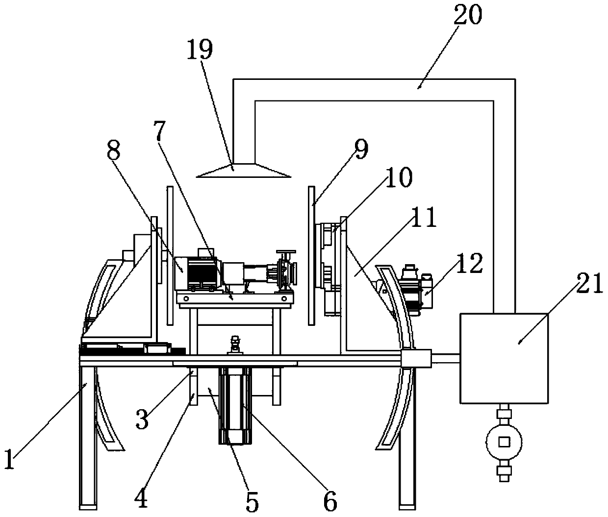
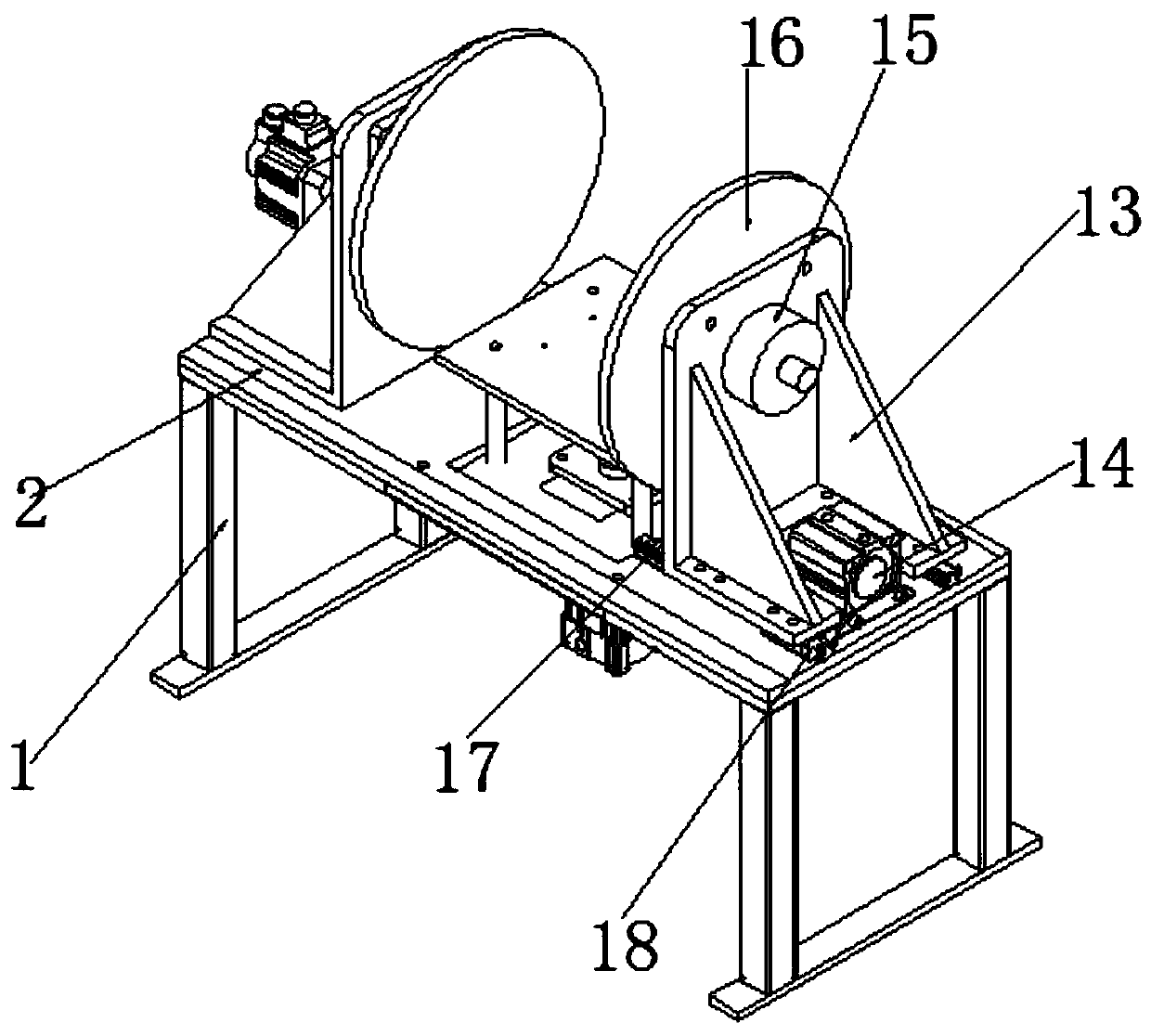
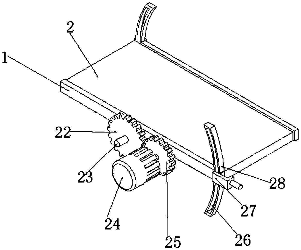
[0033] see Figure 1-5 As shown, a welding tool for pump and valve installation includes a base 1, a swivel base 2, a box body 5, a first mounting base 11, a second mounting base 13, a dust collection box 21 and a pumping tank 35, and the top side of the base 1 A swivel seat 2 is installed on the inside, and a first hydraulic rod 6 is installed at the center of the bottom of the swivel seat 2. The expansion and contraction of the first hydraulic rod 6 facilitates the adjustment of the height of the pump valve 8, which is co...


PUM


Abstract

The invention discloses a welding tool for pump valve mounting. The welding tool comprises a base, a rotating base, a box body, a first mounting base, a second mounting base, a dust collection box anda suction pressure tank. The rotating base is rotatably mounted in the top side of the base, a first hydraulic rod is mounted on the center of the bottom of the rotating base, sleeves are arranged atthe positions, on the periphery of the first hydraulic rod, in the rotating base, a mounting plate is arranged at the position, above the rotating base, of the telescopic end of the first hydraulic rod, guide rods are arranged on the periphery of the bottom of the mounting plate, the guide rods penetrate through the sleeves, one end of the rotating base is provided with a first mounting base, anda first servo motor is arranged on one side of the first mounting base. A pump valve is rapidly mounted and fixed, the pump valve can be conveniently subjected to multi-angle adjusting in the weldingprocess, the welding step is simplified, welding operation is facilitated, through stretching out and drawing back of a fourth hydraulic rod, dust treatment is finished, noise pollution is greatly reduced, and the whole treatment manner is environment-friendly, sanitary and free of pollution.

Description

technical field [0001] The invention relates to the field of pump valve installation equipment, in particular to a welding tool for pump valve installation and a welding method thereof. Background technique [0002] Pump valve is a general term for pumps and valves, not for pump valves or valves with pump function; Pumps are needed, they are all used for liquid delivery, of course, valves are also used for gas; and the pump needs to be welded during installation, and the welding tool is an important device in the welding process. [0003] When the welding step is performed in the installation of the existing pump valve, the pump valve is firstly clamped with a welding tool, and then welded, but the existing welding tool is only used to complete the fixing of the pump valve, and it cannot be adjusted according to the change of the welding angle during the welding process. Adjust the position of the pump valve, that is, welding is difficult and inconvenient for actual operati...

Claims


Application Information

Patent Timeline
IPC IPC(8): B23K37/00B23K37/04B01D46/24B08B15/00
CPCB01D46/24B08B15/007B23K37/00B23K37/0443
Inventor 柴立平徐峰张杰邓业稳许允宫克
Owner 合肥华升泵阀股份有限公司
Why Eureka
Try Eureka