

Aerated brick cutting device
A cutting device and aerated brick technology, applied in the field of aerated brick processing, can solve the problems of cutting deviation, aerated brick offset, and great effort
- Summary
- Abstract
- Description
- Claims
- Application Information
AI Technical Summary
Problems solved by technology
Method used
Image

Examples
Embodiment Construction
[0015] The following is further described in detail through specific implementation methods:
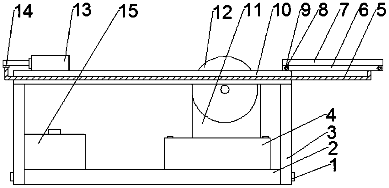
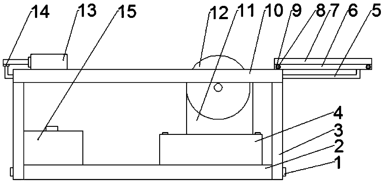
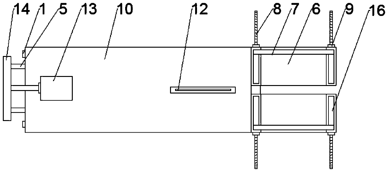
[0016] The reference signs in the drawings of the description include: screw 1, base 2, bracket 3, cushion seat 4, sliding rod 5, conveying table 6, baffle plate 7, push rod 8, lock nut 9, cutting table 10, motor 11 , cutting knife 12, cylinder 13, connecting plate 14, reinforcing seat 15, limit groove 16.
[0017] The embodiment is basically as attached figure 1 Shown: an aerated brick cutting device, including a base 2, a pedestal 4 is connected to the base 2 through a screw 1, a motor 11 is fixedly connected to the pedestal 4, a bracket 3 is threaded on the base 2 through a screw 1, and the bracket The top of 3 is welded with cutting table 10, and cutting table 10 is provided with such as figure 2 As shown in the groove, the output shaft of the motor 11 is fixedly connected with a circular cutting knife 12, the cutting knife 12 runs through the groove and cooperates with the gr...
PUM
 Abstract
Description
Claims
Application Information