Watch lens turning device

A lens and flip technology, applied in the field of watch lens detection equipment, can solve the problems of high cost, complex structure, inconvenient maintenance, etc., and achieve the effects of low cost, high efficiency and compact structure

Pending Publication Date: 2020-02-21
心鉴智控(深圳)科技有限公司
View PDF2 Cites 2 Cited by
  • Summary
  • Abstract
  • Description
  • Claims
  • Application Information

AI Technical Summary

Problems solved by technology

The structure of the above-mentioned patent is complicated, the cost is high, and it is inconvenient to maintain

Method used


Image

  • Watch lens turning device
  • Watch lens turning device
  • Watch lens turning device

Examples


Embodiment Construction

[0032] In order to enable those skilled in the art to better understand the technical solution of the present invention, the present invention will be described in further detail below in conjunction with the accompanying drawings and specific embodiments. And the features in the embodiments can be combined with each other.

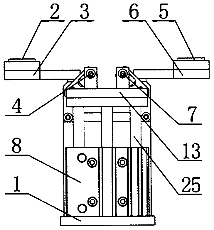
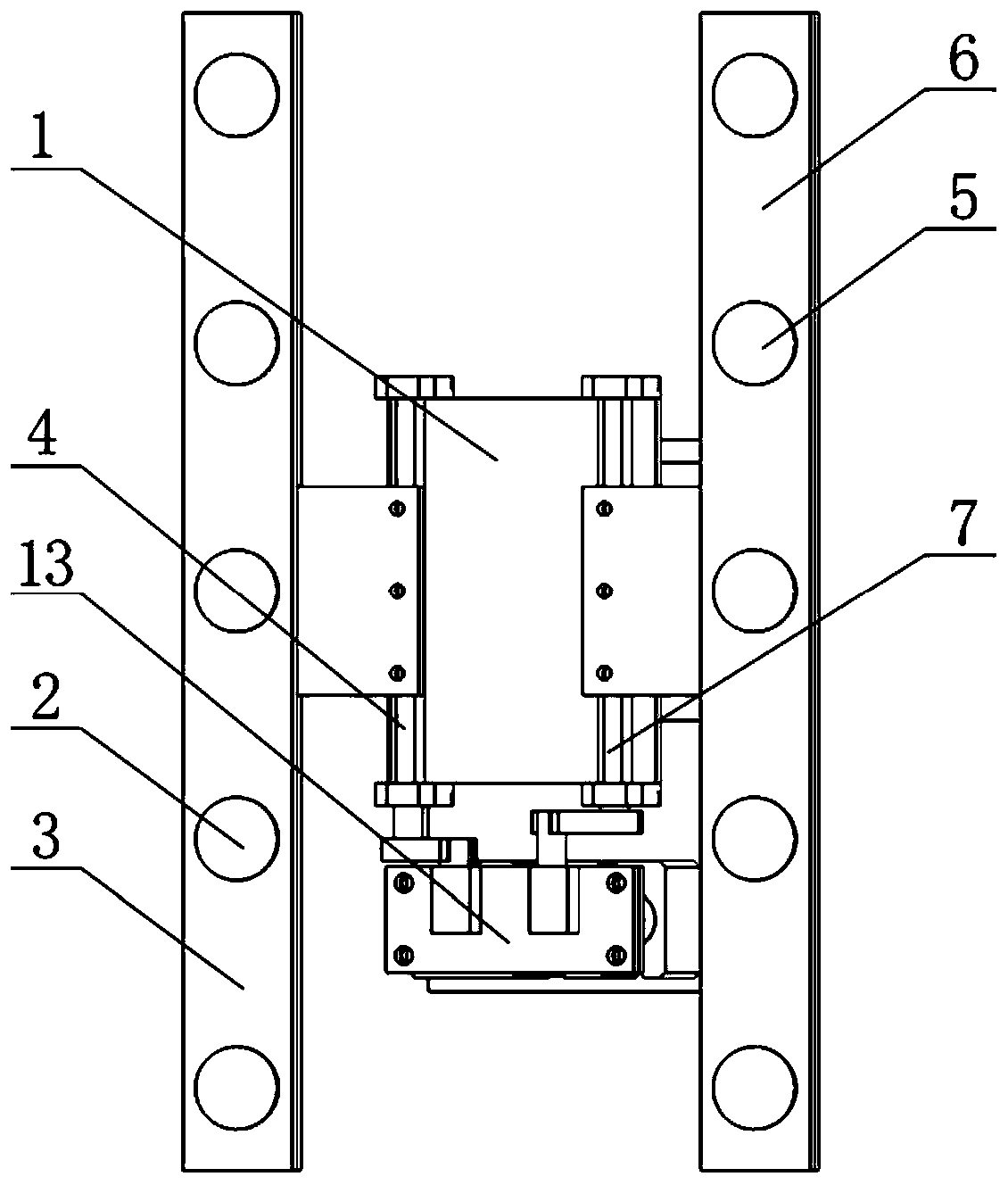
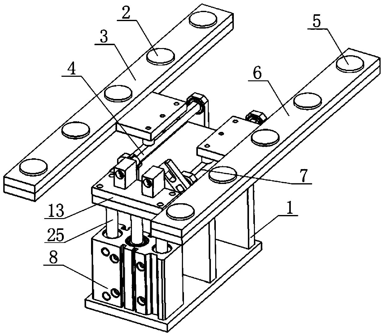
[0033] like figure 1 , 2 As shown in , 3, the watch mirror turning device includes frame 1, vacuum suction cup A2, carrier A3, rotating shaft A4, vacuum suction cup B5, carrier B6, rotating shaft B7, transmission mechanism and driving device, and the driving device adopts is cylinder 8. Described transmission mechanism comprises swing arm A9, swing arm B10, driving lever A11, driving lever B12 and lifting platform 13, and one end of swing arm A9 and one end of swing arm B10 are fixedly connected with rotating shaft A4 and rotating shaft B7 respectively, and the swing arm A4 The end face of the other end and the end face of the other end of the swing ar...


PUM


Abstract

The invention discloses a watch lens turning device. The watch lens turning device comprises a rack, a vacuum suction cup A, a carrying table A, a rotating shaft A, a vacuum suction cup B, a carryingtable B, a rotating shaft B, a transmission mechanism and a driving device, wherein the vacuum suction cup A and the vacuum suction cup B are arranged on the carrying table A and the carrying table Bcorrespondingly and correspond to each other; the vacuum suction cup A and the vacuum suction cup B are connected with a vacuum generator through pipelines correspondingly; the carrying table A and the carrying table B are mounted on the rotating shaft A and the rotating shaft B correspondingly; the rotating shaft A and the rotating shaft B are mounted on the rack in parallel; the driving device drives the rotating shaft A and the rotating shaft B to rotate through the transmission mechanism; the rotating shaft A and the rotating shaft B drive the carrying table A and the carrying table B to rotate correspondingly; the carrying table A and the carrying table B rotate to be in a vertical state from a horizontal state; and a glass sheet adsorbed to the vacuum suction cup A is adsorbed to thevacuum suction cup B. The watch lens turning device has the greatest characteristics of being simple but not simple, few in component, low in cost, high in practicability, high in efficacy and convenient to maintain.

Description

technical field [0001] The invention relates to a watch lens detection device, in particular to a watch lens turning device of the watch lens detection device. Background technique [0002] In the prior art, although components such as suction cups are also used to turn over the glass, it is not suitable for turning over the watch lens. For example, the disclosure date is July 24, 2013, and the publication number is CN 203079316 U. device. A glass turning device described in the utility model comprises a suction cup, a suction cup cylinder, a suction cup bracket, a rotating shaft, a stretching cylinder and a support frame, the suction cup is located on the bottom surface of the suction cup bracket, and the suction cup cylinder controls the suction cup and is fixed on the On the suction cup bracket, one end of the suction cup bracket is connected to the support frame through the rotating shaft, the stretching cylinder is arranged on the support frame and the piston rod of th...

Claims


Application Information

Patent Timeline
Patent Type & Authority Applications(China)
IPC IPC(8): B65G49/06
CPCB65G49/061B65G49/067
Inventor 罗晓忠孟永正熊志元
Owner 心鉴智控(深圳)科技有限公司
Why Eureka
Try Eureka