Reinforcement device and method for a curved compression bar

A reinforcement device and pressure bar technology, which is applied in construction, building maintenance, building construction, etc., can solve the problems of difficulty in making restraint parts, little contribution to stable bearing capacity, and inconvenient construction.

Active Publication Date: 2021-04-27
SOUTHEAST UNIV
View PDF7 Cites 0 Cited by
  • Summary
  • Abstract
  • Description
  • Claims
  • Application Information

AI Technical Summary

Problems solved by technology

Weld steel plates or section steel directly on the space structure rods, welding residual stress will be generated on the rods, which will have an adverse effect on the structure; paste FRP on the periphery of the rods, such as CFRP materials, although they have high strength properties, but if used to reinforce the axial For stressed members, the CFRP material contributes very little to the stable bearing capacity of the members; the bonded steel reinforcement method, first of all, the steel sheet is not easy to deform with the members, which is not convenient for construction; The strength of the glue is high, and it is also required to withstand fatigue load and anti-aging
And after the above method is used to strengthen, when the axial pressure is large, the buckling instability of the member will still occur.
[0005] The Chinese patent with the application number 201510423508.7 discloses a method for strengthening key members of space structures, which is composed of steel plates and section steel through unilateral bolts to form a square restraint component. When the key member is a curved member and the initial deflection is uncertain, such as Using the method proposed in the above patent will require reinforcement and restraint parts of various specifications, which will bring difficulties to the manufacture of restraint parts

Method used


Image

  • Reinforcement device and method for a curved compression bar
  • Reinforcement device and method for a curved compression bar
  • Reinforcement device and method for a curved compression bar

Examples


Embodiment 1

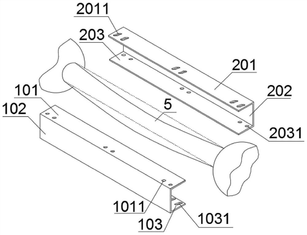
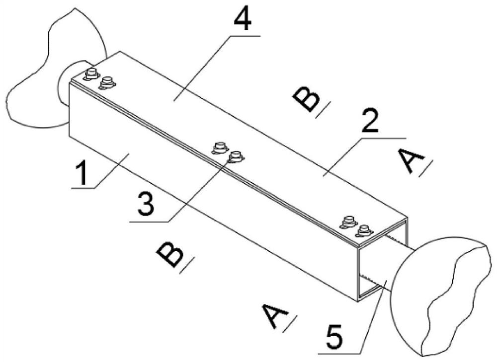
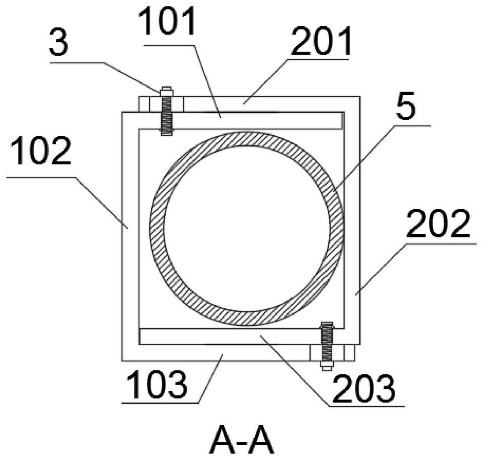
[0035] Such as Figure 1~6 , the curved compression bar 5 is in the shape of a curved round bar, and the reinforcing components used are two first U-shaped steel 1 and second U-shaped steel 2 whose length is slightly shorter than the curved compression bar 5 . A round hole 1011 is formed on the first flange 101 of the first U-shaped steel 1 , and a slot 1031 is formed on the second flange 103 . There is a second slot hole 2011 on the third flange 201 of the second U-shaped steel 2 , and a second round hole 2031 is arranged on the fourth flange 203 . The first U-shaped steel 1 and the second U-shaped steel 2 are identical. The first flange 101 , the second flange 103 , the third flange 201 , and the fourth flange 203 are parallel to the initial deflection direction of the bending strut 5 . The first U-shaped steel 1 and the second U-shaped steel 2 are arranged oppositely, the first flange 101 overlaps the third flange 201 , and the second flange 103 overlaps the fourth flange...

Embodiment 2

[0037] Such as Figure 7~10 , The difference between this embodiment and Embodiment 1 is that the two ends of the bending bar 5 are welded with stiffeners 6 along the axial direction of the bent bar 5 close to the support, and two stiffeners 6 are welded symmetrically at each end, and the stiffeners 6 are welded at the restraining part In the gap formed by the corner of 4 and the surface of the curved strut 5. The length of the stiffener 6 is greater than the cross-sectional outer diameter of the bent strut 5 . A positioning pin 7 is arranged in the middle of the bending compression bar 1, and the positioning pin 7 passes through the first web 102 or the second web 202, and other parts are the same as in the first embodiment.

Embodiment 3

[0039] Such as Figure 11 The difference between this embodiment and Embodiment 1 is that after the first U-shaped steel 1 and the second U-shaped steel 2 are overlapped by dislocation, the tail of the third flange 201 can be welded to the first flange 101 through the welding seam 8 , the tail of the second flange 103 is welded on the fourth flange 203, and other parts are the same as in Embodiment 1.


PUM


Abstract

The invention discloses a reinforcement device and a reinforcement method for a curved compression bar. The reinforcement device includes a first U-shaped steel and a second U-shaped steel; the first U-shaped steel includes a first flange, a first web and a second wing The first flange is provided with a round hole 1, and the second flange is provided with a slot hole 1; the second U-shaped steel includes a third flange, a second web and a fourth flange, and a slot hole is arranged on the third flange 2. There is round hole 2 on the fourth flange; round hole 1 and slot hole 2 are fixed by unilateral bolts, slot 1 and round hole 2 are fixed by unilateral bolts. The reinforcing method comprises the following steps: respectively opening the first round hole, the first slot hole, the second slot hole, and the second round hole, and the flange is parallel to the initial deflection direction of the curved compression bar; Fastened by single side bolts. The invention does not need to change the size of the U-shaped steel, and "adapts" to bending compression bars with different deflections through the slots on the flange, and can be reinforced with the same U-shaped steel, which is beneficial to improving the adaptability of engineering applications.

Description

technical field [0001] The invention belongs to the field of space structure reinforcement, in particular to a reinforcement device and a reinforcement method for a curved compression bar. Background technique [0002] At present, people have higher and higher requirements for the unshielded space of large buildings, and it is difficult for the original structural form to meet these requirements. The large-span space structure is currently the fastest-growing structure type, and the development status of the space structure technology as its core is one of the important symbols representing a country's architectural technology level. [0003] The damage of space structure is usually caused by the instability of key members. Taking the grid structure as an example, its key members generally refer to some upper chords in the span. Under the action of strong wind or strong earthquake, the upper chord of the mid-span of the grid structure first undergoes elastic buckling, the ...

Claims


Application Information

Patent Timeline
Patent Type & Authority Patents(China)
IPC IPC(8): E04G23/02
CPCE04G23/0225
Inventor 王春林曾滨卿缘言炘
Owner SOUTHEAST UNIV
Why Eureka
Try Eureka