Pipe laying device and laying method for road engineering

A road engineering and pipeline technology, which is applied in the field of pipeline laying devices for road engineering, can solve the problems of low work efficiency, long time consumption, and pipeline offset and falling off, and achieves the effects of reducing labor intensity, fixing firmly, and improving work efficiency.

Active Publication Date: 2021-04-02
苏州科亿嘉科技发展有限公司
View PDF12 Cites 0 Cited by
  • Summary
  • Abstract
  • Description
  • Claims
  • Application Information

AI Technical Summary

Problems solved by technology

[0005] The purpose of the present invention is to provide a pipe laying device for road engineering and its laying method, to solve the problem that most of the current road engineering pipes are laid by several workers using clamps to lift the pipes to the laying position, and then connect the pipes. Fixing; it is impossible to control the two cantilevers to automatically clamp and fix the pipeline. Workers need to manually fix the cantilever and the pipeline. The operation is cumbersome. It takes a long time to fix the two cantilevers and the pipeline; For heavy pipes, most of them use ropes to tie up and fix the pipes, and then use a crane to lift and move them. Multiple workers are required to support and fix the pipes to avoid turning of the pipes. It is difficult to move and inconvenient to use. When transporting short pipes, only A single pipeline is transported, and the work efficiency is low; the existing pipeline clamping device has no fixed structure between the pipeline and the two cantilevers, and the pipeline has the risk of deviation and falling off during transportation

Method used


Image

  • Pipe laying device and laying method for road engineering
  • Pipe laying device and laying method for road engineering
  • Pipe laying device and laying method for road engineering

Examples


Embodiment Construction

[0034] The technical solutions of the present invention will be clearly and completely described below in conjunction with the embodiments. Apparently, the described embodiments are only some of the embodiments of the present invention, not all of them. Based on the embodiments of the present invention, all other embodiments obtained by persons of ordinary skill in the art without creative efforts fall within the protection scope of the present invention.

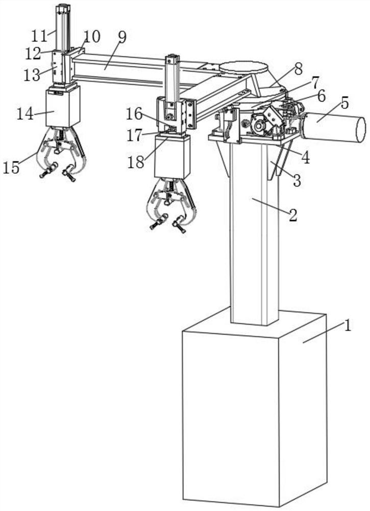
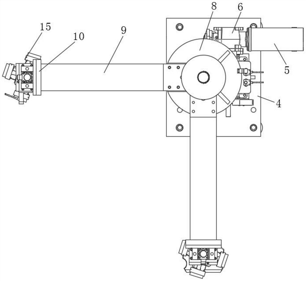
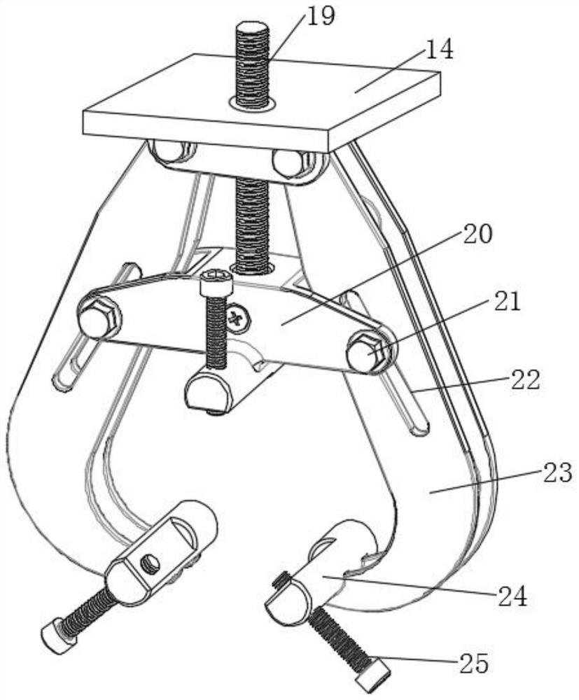
[0035] Such as Figure 1-6 As shown, a pipeline laying device for road engineering includes a first hydraulic cylinder 1, a horizontal plate 9 and a clamping device 15. The inside of the first hydraulic cylinder 1 is provided with a first hydraulic rod 2, and the first hydraulic rod 2 The top of the top is fixedly provided with a fixed plate 4, and two support plates 3 are respectively arranged between the side walls on both sides of the fixed plate 4 and the bottom surfaces on both sides of the first hydraulic rod 2, and t...


PUM


Abstract

The invention discloses a pipeline laying and arranging device for road engineering. The pipeline laying and arranging device for the road engineering comprises a first hydraulic cylinder, a transverse plate and a clamping device, a first hydraulic rod is arranged inside the first hydraulic cylinder, a fixing plate is fixedly arranged at the top of the first hydraulic rod, and two supporting plates are arranged between the side wall of each of the two sides of the fixing plate and the bottom surface of the corresonding one of the two sides of the first hydraulic rod. A work box is rotated, sothat a rotating block rotates inside a circular frame, two cantilevers are adjusted in different clamping directions, the situation that short pipes are in mutual contact to influence laying and arranging is avoided, the two short pipes can be laid and arranged at the same time, so that the working efficiency is improved, when a long pipe is laid and arranged, the work box is rotated, so that therotating block rotates inside the circular frame, the clamping directions of the two cantilevers are adjusted to be consistent, the two ends of the long pipe are clamped correspondingly, fixation of the long pipe is achieved, the long pipe is fixed more firmly, the risk that the long pipe slides off the clamping device is avoided, the construction safety is improved, and the equipment can performlaying and arranging work on pipelines with different length sizes.

Description

technical field [0001] The invention relates to the field of equipment for road engineering, in particular to a pipe laying device for road engineering and a laying method thereof. Background technique [0002] Road engineering refers to the whole process of planning, design, construction, maintenance and management with roads as the object and the engineering entities involved. At present, when laying road engineering pipelines, most of them use cranes or manual lifting of pipelines for positioning. The mobile adjustment, the work efficiency is low, and the labor intensity of the workers is high. [0003] Publication number is the Chinese patent of CN103174108B, discloses a kind of non-skateboard laying ship transmission type laying device, and this laying device comprises the roller that is arranged on the side of the laying ship and the transmission device in the hull, described roller, transmission device and side The side decks are connected by conveyor belts. The inv...

Claims


Application Information

Patent Timeline
Patent Type & Authority Patents(China)
IPC IPC(8): F16L1/06B66C23/02B66C23/62B66C23/84B66C1/42
CPCB66C1/42B66C23/02B66C23/62B66C23/84F16L1/06
Inventor 张德君
Owner 苏州科亿嘉科技发展有限公司
Why Eureka
Try Eureka