Sampling apparatus using remote automatic control for transported lime powder of tank car

A technology of sampling device and tank truck, which is applied in the direction of sampling device, program control, general control system, etc., can solve the problems of incomplete samples and inaccurate data, and achieve the effect of expanding the sampling range, accurate data and expanding the sampling range

Pending Publication Date: 2020-02-21
ZHANGJIAGANG HONGCHANG STEEL PLATE CO LTD +1
0 Cites 1 Cited by

AI-Extracted Technical Summary

Problems solved by technology

However, the current lime powder sampling is generally carried out by opening the cover of the tank truck, which is often only partially...

Method used

With reference to accompanying drawing 1-5 of specification sheet, drive screw mandrel 7 to rotate by motor 5 output ends, screw mandrel 7 drives slide block 24 to slide to the right, thereby drives material box 9 to move to the right by support plate 13, when material When the box 9 moves to the right, the inner rod 142 will slide downward under the force of the spring 143, thereby driving the support plate 13 and the material box 9 to move downward, and the material box 9 moves downward to the inside of the lime powder while moving to the right At this time, the output end of the electric push rod 12 drives the rubber plug 11 to move upward, and a negative p...

Abstract

The invention discloses a sampling apparatus using remote automatic control for transported lime powder of a tank car, and specifically relates to the technical field of lime power sampling. The sampling apparatus includes a vertical plate; a frame is disposed on one side of the vertical plate; a transmission mechanism is disposed inside the frame; a sampling mechanism is disposed on a bottom endof the frame; the transmission mechanism includes a motor, a slide plate, a screw rod and a guide rod; the screw rod is fixedly connected to an output end of the motor; the slide plate is slidably connected to the inside of the frame; both the screw rod and the guide rod penetrate through the slide plate; the screw rod is in threaded connection with the slide plate; and the sampling mechanism includes a material box. According to the sampling apparatus provided by the invention, the motor rotates reversely to drive the material box to move leftward; a bump is squeezed by the guide rod in a movement process, so that the material box moves upward while moving leftward, and the material box samples while moving; and therefore, the sampling range is larger, the sampled specimen is more complete, and the data obtained in later analysis is more accurate.

Application Domain

Withdrawing sample devicesProgramme control in sequence/logic controllers

Technology Topic

Electric machineryAutomatic control +5

Image

  • Sampling apparatus using remote automatic control for transported lime powder of tank car
  • Sampling apparatus using remote automatic control for transported lime powder of tank car
  • Sampling apparatus using remote automatic control for transported lime powder of tank car

Examples

  • Experimental program(1)

Example Embodiment

[0026] The technical solutions in the embodiments of the present invention will be clearly and completely described below in conjunction with the accompanying drawings in the embodiments of the present invention. Obviously, the described embodiments are only a part of the embodiments of the present invention, rather than all the embodiments. Based on the embodiments of the present invention, all other embodiments obtained by those of ordinary skill in the art without creative work shall fall within the protection scope of the present invention.
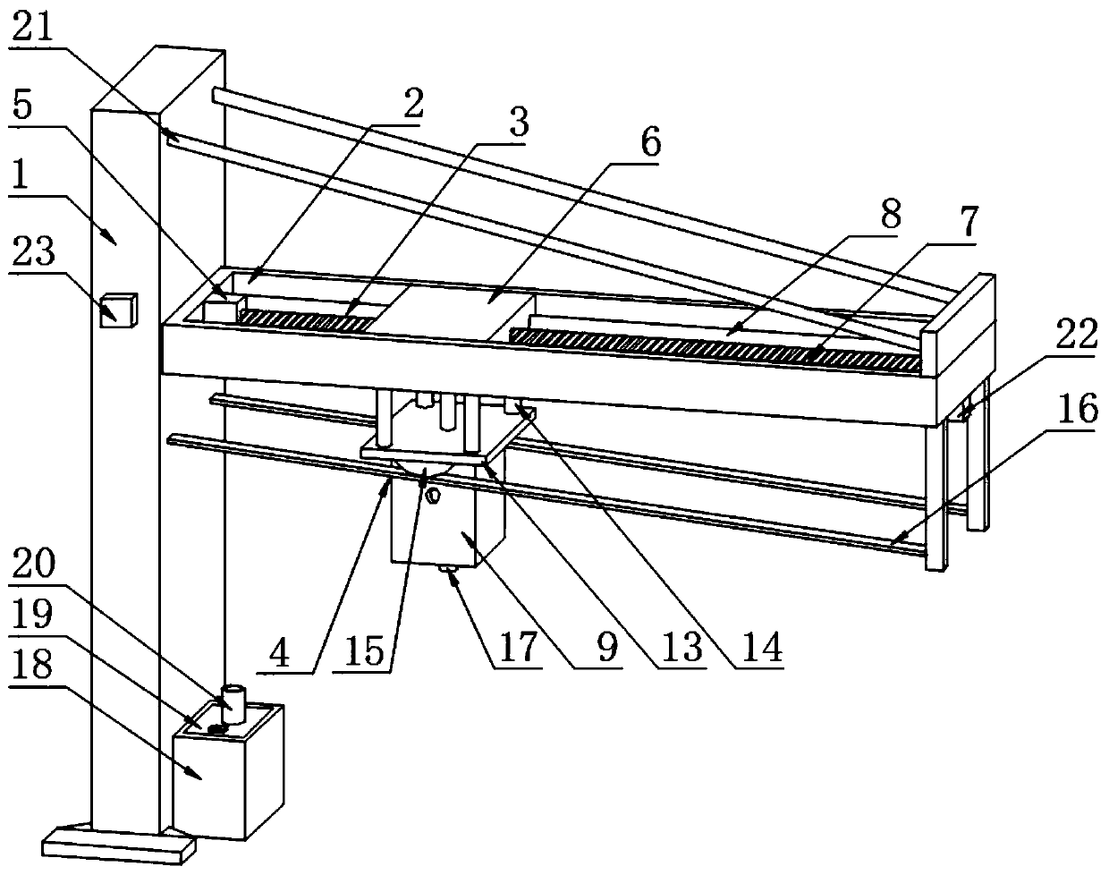
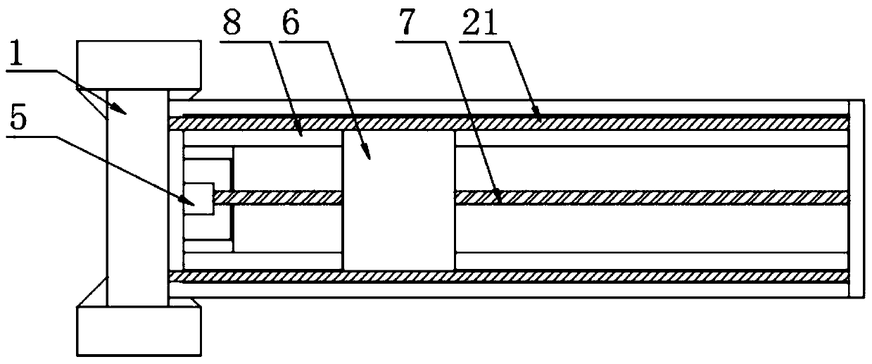
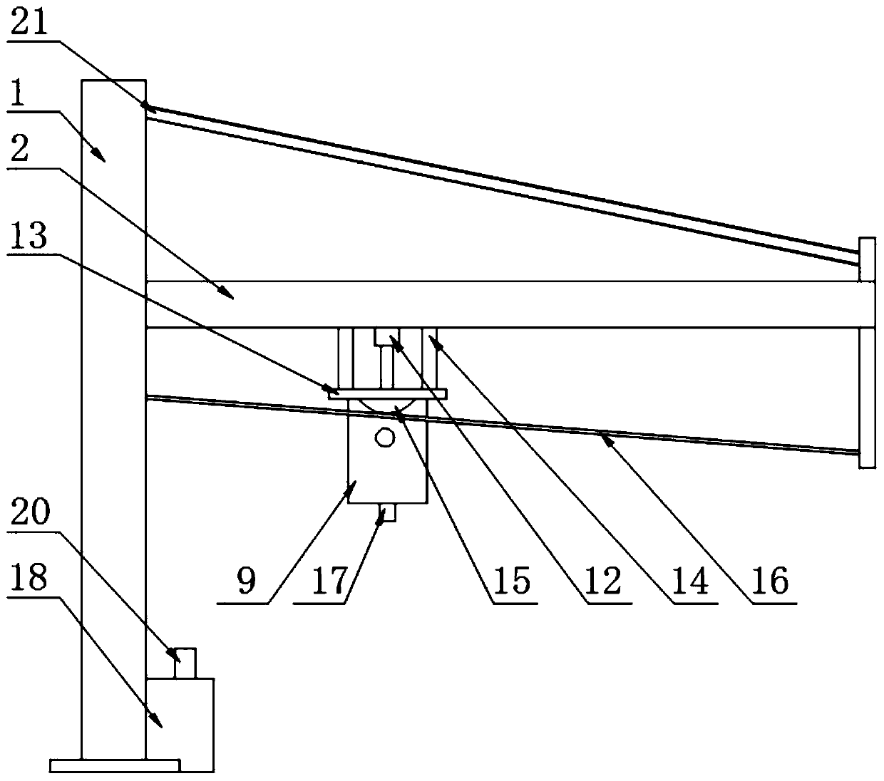
[0027] The present invention provides Figure 1-5 A sampling device for transporting lime powder using a remote automatic control tank truck is shown, which includes a vertical plate 1, a frame 2 is provided on one side of the vertical plate 1, and a transmission mechanism 3 is provided inside the frame 2. 2 A sampling mechanism 4 is provided at the bottom end;
[0028] The transmission mechanism 3 includes a motor 5, a sliding plate 6, a screw rod 7 and a guide rod 8. The screw rod 7 is fixedly connected to the output end of the motor 5, the sliding plate 6 is slidably connected to the inside of the frame 2, and the screw rod 7 and The guide rods 8 pass through the sliding plate 6, and the screw rod 7 is threadedly connected with the sliding plate 6;
[0029] The sampling mechanism 4 includes a material box 9 with feed inlets on both front and rear sides of the material box 9, a vent tube 10 is provided at the top of the material box 9 and a rubber plug 11 is provided inside the vent tube 10, so The top of the rubber plug 11 is provided with an electric push rod 12, the output shaft of the electric push rod 12 is fixedly connected with the rubber plug 11, and the top of the material box 9 is fixedly connected with a supporting plate 13 between the supporting plate 13 and the sliding plate 6. A telescopic assembly 14 is provided. The telescopic assembly 14 includes an outer rod 141, an inner rod 142, and a spring 143. The inner rod 142 is slidably connected to the bottom end of the outer rod 141, and the top of the outer rod 141 is fixedly connected to the sliding plate 6, so The bottom of the inner rod 142 is fixedly connected to the support plate 13, the spring 143 is fixedly connected between the outer rod 141 and the support plate 13, and the spring 143 is arranged outside the inner rod 142. A convex block 15 is fixedly connected, the convex block 15 is arranged in a semicircular shape, the bottom of the convex block 15 is provided with a guide rod 16, and the guide rod 16 is inclinedly arranged;
[0030] The guide rod 8 is arranged on the front and rear sides of the screw rod 7, the guide rod 8 is fixedly connected to the front and rear sides of the frame 2, the screw rod 7 is slidably connected to the slide plate 6, and the screw rod 7 is rotatably connected to the frame 2. Inside, the guide rod 8 is conducive to the screw rod 7 to drive the skateboard 6 back and forth;
[0031] The vent tube 10 penetrates the material box 9 and extends to the inside of the material box 9, and the electric push rod 12 is fixedly connected to the sliding plate 6;
[0032] A control valve 17 is provided at the bottom of the material box 9, a receiving box 18 is provided on one side of the vertical plate 1, a cover plate 19 is hingedly connected to the top of the receiving box 18, and the top side of the cover plate 19 is fixedly connected with Handle, the top of the cover plate 19 is provided with a feed pipe 20, the feed pipe 20 penetrates the cover plate 19 and extends to the inside of the receiving box 18. The control valve 17 is helpful for conveying the lime powder inside the material box 9 to the receiving box. Inside the material box 18;
[0033] A first baffle is fixedly connected to the top side of the frame 2, and a wire rope 21 is fixedly connected between the first baffle and the vertical plate 1. The first baffle is beneficial to fix the wire rope 21;
[0034] A second baffle is fixedly connected to the bottom side of the frame 2, and the guide rod 16 is fixedly connected between the vertical plate 1 and the second baffle, and the second baffle is beneficial to fix the guide rod 16;
[0035] A base is fixedly connected to the bottom of the motor 5, the base is fixedly connected to the frame 2, the front and rear sides of the bottom of the vertical plate 1 are fixedly connected with mounting plates, and the slide plate 6 is fixedly connected with sliders on both front and rear sides 24. The frame 2 is provided with sliding grooves on both front and rear sides, the sliding block 24 is slidably connected to the inside of the sliding groove, and the base is beneficial to fix the motor 5;
[0036] The specific implementation is as follows: by providing a motor 5 inside the frame 2, the output end of the motor 5 drives the screw rod 7 to rotate, and the screw rod 7 is slidably connected to the slider 24. With the cooperation of the guide rod 8, the screw rod 7 rotates to drive the sliding The block 24 slides to the right, and the sliding block 24 drives the support plate 13 to move to the right through the telescopic assembly 14, thereby bringing the animal material box 9 to move to the right. When the material box 9 moves to the right, it is internally under the force of the spring 143 The rod 142 will slide downwards, thereby driving the support plate 13 and the material box 9 to move downwards. The cooperation of the protrusion 15 and the guide rod 16 makes the movement of the support plate 13 more stable, and the guide rod 16 also plays a supporting role. When the material box 9 moves to the right, it moves down to the inside of the lime powder. At this time, the output end of the electric push rod 12 can drive the rubber plug 11 to move upward. At this time, a negative pressure is formed inside the material box 9 and the lime is under the action of the pressure difference. The powder is pressed into the material box 9 through the feed port to realize the sampling of lime powder. After that, the motor 5 is reversed, and the sliding plate 6, the support plate 13 and the material box 9 are driven to the left by the screw rod 7. The block 15 will squeeze the guide rod 16 during the movement, thereby driving the support plate 13 and the material box 9 to move upward under the squeezing of the guide rod 16, so that the material box 9 moves upward while moving to the left, and at the same time it is electric The push rod 12 always pulls the rubber stopper 11 to move upwards, so that the material box 9 moves while sampling. In this way, the sampling range is larger and the sample drawn is more comprehensive, so that the data obtained in the later analysis is more accurate, and then the control valve 17 and the feed pipe 20 are connected by a hose, and the control valve 17 is opened to deliver the lime powder to the inside of the receiving box 18 for easy access. This embodiment specifically solves the problem of expanding the sampling range in the lime powder sampling process in the prior art , So as to get a more comprehensive sample of questions.
[0037] The present invention provides figure 1 with 6 A sampling device for transporting lime powder in a tank truck with remote automatic control is shown. A proximity sensor 22 is provided on the bottom side of the frame 2 and a PLC controller 23 is provided on the front side of the vertical rod. The proximity sensor 22 is beneficial to Detect the location of the vehicle;
[0038] The input terminal of the PLC controller 23 is provided with an A/D converter, the output terminal of the PLC controller 23 is provided with a D/A converter, the proximity sensor 22 is electrically connected to the A/D converter, and the motor 5 and the electric push rod 12 are electrically connected to the D/A converter;
[0039] The specific implementation is as follows: the model of the proximity sensor 22 is set to IM12-D1LA04, and the model of the PLC controller 23 is set to TL2N-14MR-2V, which are all existing technologies. When sampling, when the vehicle approaches the frame 2, it approaches The sensor 22 converts the analog signal into an electrical signal and transmits it to the A/D converter. The A/D converter transmits the digital signal to the PLC controller 23 for analysis and processing, and then transmits the processed data to the D/A converter, thereby Through the D/A converter to control the work of the motor 5 and the electric push rod 12, this system can quickly and easily control the motor 5 and the electric push rod 12, and can realize remote control, which is more intelligent to use. This implementation mode The problem of using remote intelligent control of electrical appliances in the prior art is specifically solved.
[0040] The working principle of the present invention:
[0041] Refer to the instructions attached Figure 1-5 , The screw rod 7 is driven to rotate by the output end of the motor 5, and the screw rod 7 drives the sliding block 24 to slide to the right, so that the animal material box 9 is moved to the right through the support plate 13. When the material box 9 moves to the right, the spring 143 Under the force of, the inner rod 142 will slide down, thereby driving the support plate 13 and the material box 9 to move downwards. The material box 9 moves to the right while moving down to the inside of the lime powder. At this time, the output end of the electric push rod 12 The rubber plug 11 is driven to move upwards, and negative pressure is formed inside the material box 9. Under the action of the pressure difference, the lime powder is pressed into the material box 9 through the inlet, so as to realize the sampling of the lime powder, and then the motor 5 is reversed. Drive the sliding plate 6, the support plate 13 and the material box 9 to move to the left. At this time, the bump 15 will squeeze the guide rod 16 during the movement, thereby driving the support plate 13 and the material box 9 to move upward, making the material box 9 move to the left Move upward while moving, and the material box 9 is moved while sampling through the electric push rod 12, which can expand the sampling range;
[0042] Refer to the instructions attached figure 1 with 6 When the vehicle approaches the frame 2, the proximity sensor 22 converts the analog signal into an electrical signal and transmits it to the A/D converter, and the A/D converter transmits the digital signal to the PLC controller 23 for analysis and processing, and then the processed data It is transmitted to the D/A converter to control the work of the motor 5 and the electric push rod 12 through the D/A converter. Through this system, the motor 5 and the electric push rod 12 can be controlled quickly and conveniently, and remote control can be realized. .
[0043] The last points that should be explained are: First of all, in the description of this application, it should be noted that, unless otherwise specified and limited, the terms "installation", "connected", and "connected" should be understood in a broad sense and can be mechanically connected. Or electrical connection, it can also be the internal connection of two components, it can be directly connected, "up", "down", "left", "right", etc. are only used to indicate the relative position relationship, when the absolute position of the object being described Change, the relative position relationship may change;
[0044] Secondly: In the drawings of the disclosed embodiments of the present invention, only the structures related to the embodiments of the present disclosure are involved. Other structures can refer to the usual design. In the case of no conflict, the same embodiment and different embodiments of the present invention can be combined with each other;
[0045] Finally: the above are only the preferred embodiments of the present invention and are not intended to limit the present invention. Any modification, equivalent replacement, improvement, etc. made within the spirit and principle of the present invention shall be included in the present invention Within the scope of protection.

PUM

no PUM

Description & Claims & Application Information

We can also present the details of the Description, Claims and Application information to help users get a comprehensive understanding of the technical details of the patent, such as background art, summary of invention, brief description of drawings, description of embodiments, and other original content. On the other hand, users can also determine the specific scope of protection of the technology through the list of claims; as well as understand the changes in the life cycle of the technology with the presentation of the patent timeline. Login to view more.

Similar technology patents

Method for measuring flood discharge atomization rainfall capacity

PendingCN109633791Aaccurate data
Owner:NANJING HYDRAULIC RES INST +1

Application management and control method for SSR centralized management platform

InactiveCN108830075ARich sources of dataaccurate data
Owner:ZHENGZHOU YUNHAI INFORMATION TECH CO LTD

Visibility analysis method based on camera image

PendingCN109978842Arich sample
Owner:藏龙信息科技(苏州)有限公司

Electronic livestock scale

InactiveCN102435272AEasy weighing processaccurate data
Owner:常熟市佳衡天平仪器有限公司

Method for establishing post-coronary artery bypass transplantation acute kidney injury prediction model

PendingCN112837819Alarge baserich sample
Owner:FUWAI HOSPITAL CHINESE ACADEMY OF MEDICAL SCI

Calibration device and calibration method for radio frequency homing-based semi-physical simulation system

InactiveCN104516348ACalibration progress highaccurate data
Owner:GUIZHOU AEROSPACE INST OF MEASURING & TESTING TECH

Classification and recommendation of technical efficacy words

  • rich sample

Visibility analysis method based on camera image

PendingCN109978842Arich sample
Owner:藏龙信息科技(苏州)有限公司

Method for establishing post-coronary artery bypass transplantation acute kidney injury prediction model

PendingCN112837819Alarge baserich sample
Owner:FUWAI HOSPITAL CHINESE ACADEMY OF MEDICAL SCI
Why Eureka
Try Eureka