Display panel, visual angle control method of display panel, and display device
A display panel, viewing angle control technology, applied in instruments, nonlinear optics, optics, etc., can solve the problems of gray scale inversion, whitening on both sides of the panel, etc.
- Summary
- Abstract
- Description
- Claims
- Application Information
AI Technical Summary
Problems solved by technology
Method used
Image
Examples
no. 1 example
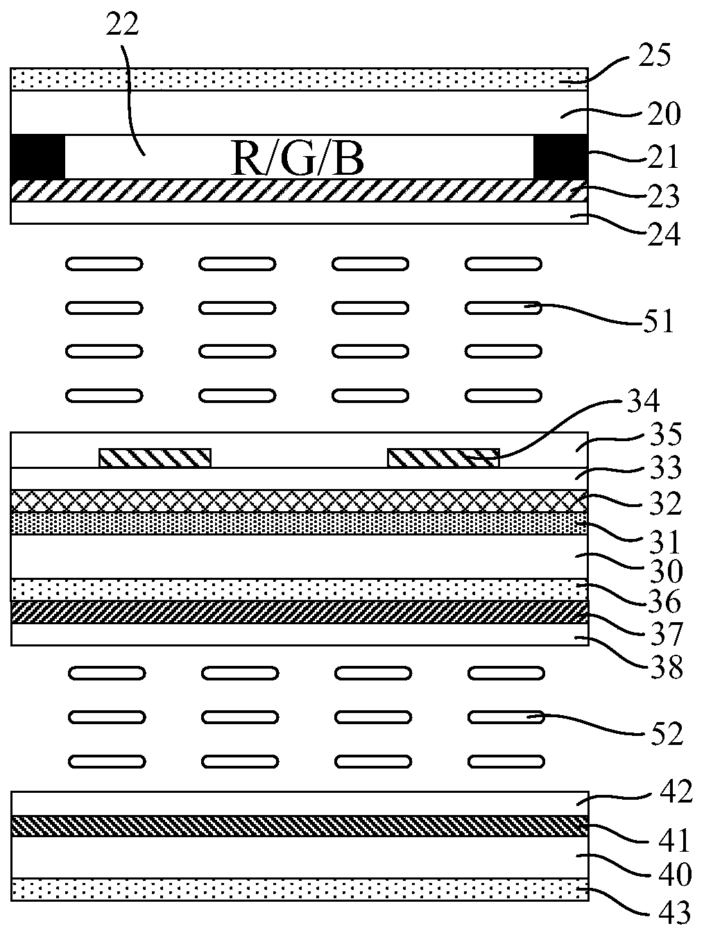
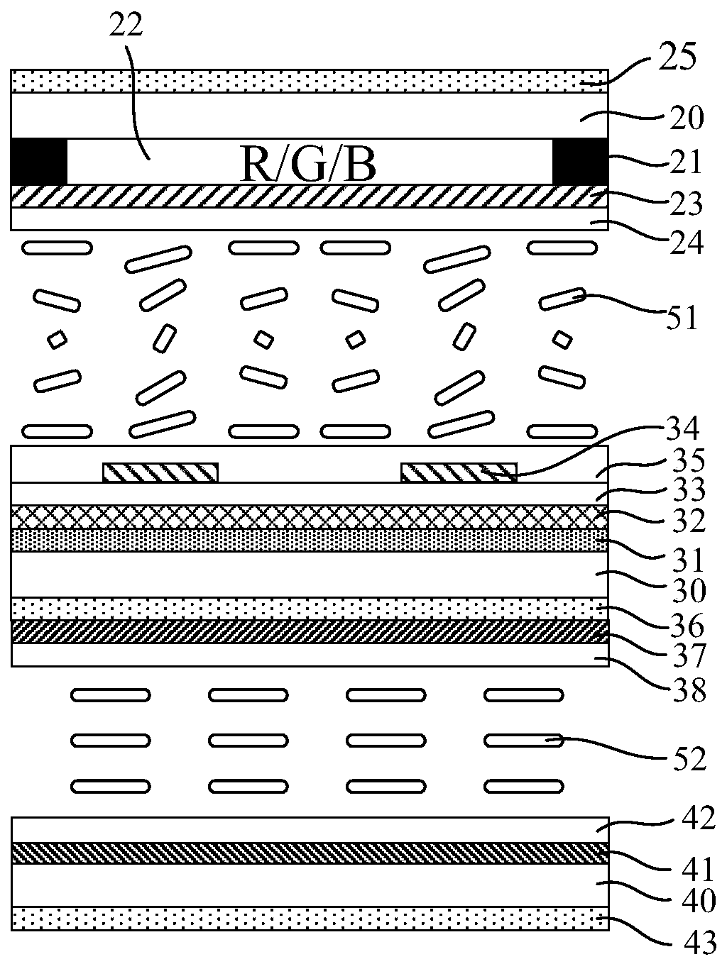
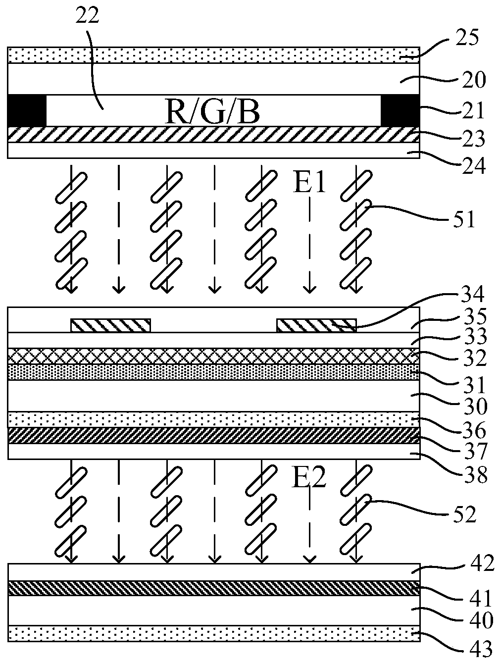
[0039] Please refer to Figure 1(a) to Figure 2(b), FIG. 1(a) shows a schematic structural view of the dark state of the display panel in the wide viewing angle mode according to the first embodiment of the present invention, and FIG. 1(b) shows a schematic structural view of the bright state of the display panel in the wide viewing angle mode ; FIG. 2(a) shows a schematic structural view of the display panel in a dark state in a narrow viewing angle mode, and FIG. 2(b) shows a schematic structural view of the display panel in a bright state in a narrow viewing angle mode. The display panel provided by the first embodiment of the present invention includes a first substrate 20, a first liquid crystal layer 51, a second substrate 30, a second liquid crystal layer 52 and a third substrate 40, and the first liquid crystal layer 51 is sandwiched between the first substrate 20 and the third substrate 40. The first liquid crystal cell is formed between the second substrates 30 , and...
no. 2 example
[0066] Please refer to Image 6 with Figure 7 , respectively show the structural diagrams of the display panel in the wide viewing angle mode and the narrow viewing angle mode of the second embodiment of the present invention. The difference from the first embodiment above is that the second liquid crystal layer 52 uses negative liquid crystal, and the second The initial pretilt angle of the negative liquid crystal in the liquid crystal layer 52 relative to the second substrate 30 and the third substrate 40 is between 30°-85°.
[0067] Please refer to Image 6 , in the wide viewing angle mode, the voltage difference between the first electrode 23 and the common electrode 32 is zero or small, and there is a large voltage difference between the second electrode 37 and the third electrode 41 . Please refer to Figure 7 , in the narrow viewing angle mode, there is a large voltage difference between the first electrode 23 and the common electrode 32 , and the voltage difference...
no. 3 example
[0074] Please refer to Figure 8 with Figure 9 , respectively show the structure diagrams of the display panel in the wide viewing angle mode and the narrow viewing angle mode of the third embodiment of the present invention, the difference from the above first embodiment is that the first liquid crystal layer 51 adopts negative liquid crystal, and the first The initial pretilt angle of the negative liquid crystal in the liquid crystal layer 51 relative to the first substrate 20 and the second substrate 30 is between 30°-85°.
[0075] Please refer to Figure 8 , in the wide viewing angle mode, there is a large voltage difference between the first electrode 23 and the common electrode 32 , and the voltage difference between the second electrode 37 and the third electrode 41 is zero or small. Please refer to Figure 9 , in the narrow viewing angle mode, the voltage difference between the first electrode 23 and the common electrode 32 is zero or small, and there is a large vo...
PUM
 Abstract
Description
Claims
Application Information
 - R&D
- Intellectual Property
- Life Sciences
- Materials
- Tech Scout
- Unparalleled Data Quality
- Higher Quality Content
- 60% Fewer Hallucinations
Browse by: Latest US Patents, China's latest patents, Technical Efficacy Thesaurus, Application Domain, Technology Topic, Popular Technical Reports.
© 2025 PatSnap. All rights reserved.Legal|Privacy policy|Modern Slavery Act Transparency Statement|Sitemap|About US| Contact US: help@patsnap.com


