
Overcurrent processor for electric power

A current protector, used technology, applied in the direction of circuits, electrical components, parts of protection switches, etc., can solve the problems of reduced life, large mechanical stress, aging of electrical components, etc., to reduce the amount of current, avoid damage, good blocking effect

Inactive Publication Date: 2020-02-21
曲相霖
View PDF4 Cites 7 Cited by
  • Summary
  • Abstract
  • Description
  • Claims
  • Application Information

AI Technical Summary

Problems solved by technology

[0003] In the use of household electrical appliances, the treatment methods for overload current and short-circuit current are different. The current of overload current is generally not many times the current carrying capacity of the circuit. shortening, after a period of time, it will cause disasters and cause damage to electrical appliances. The damage is caused by the accumulation of time. For short-circuit currents, the current value can reach hundreds or even thousands of times the current carrying capacity of the loop conductor, which can produce Abnormal high temperature or huge mechanical stress cause various disasters. Therefore, in the prior art, the use principle of fuses is the melting and decomposition of low-melting point metals. For the overload current, the circuit will generally only be disconnected after the accumulated temperature reaches the fusing temperature of the fuse after a period of time. In a certain period of time, it will still cause problems such as aging of electrical components and reduced life span, and the fuse of the fuse can only be used once and needs to be replaced every time it is used. Based on this, the present invention designs an overcurrent processor for electric power

Method used


Image

  • Overcurrent processor for electric power
  • Overcurrent processor for electric power
  • Overcurrent processor for electric power

Examples


Embodiment

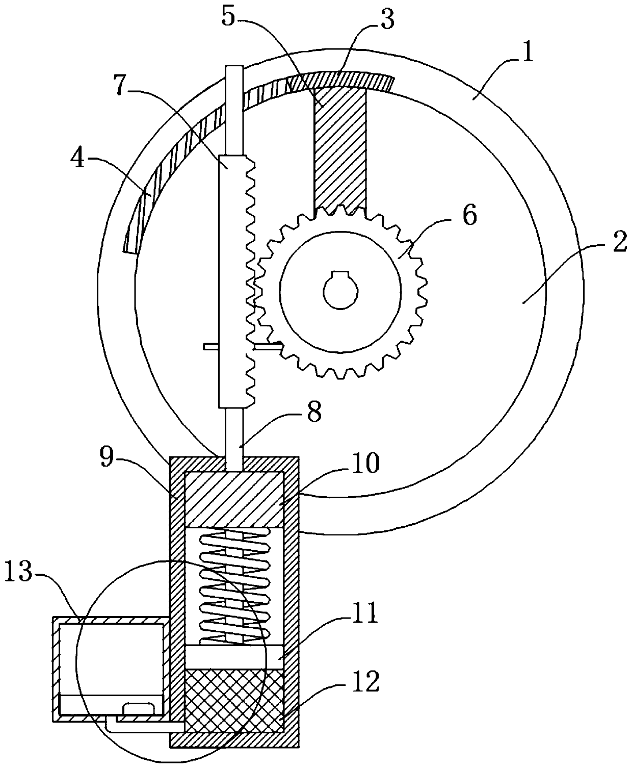
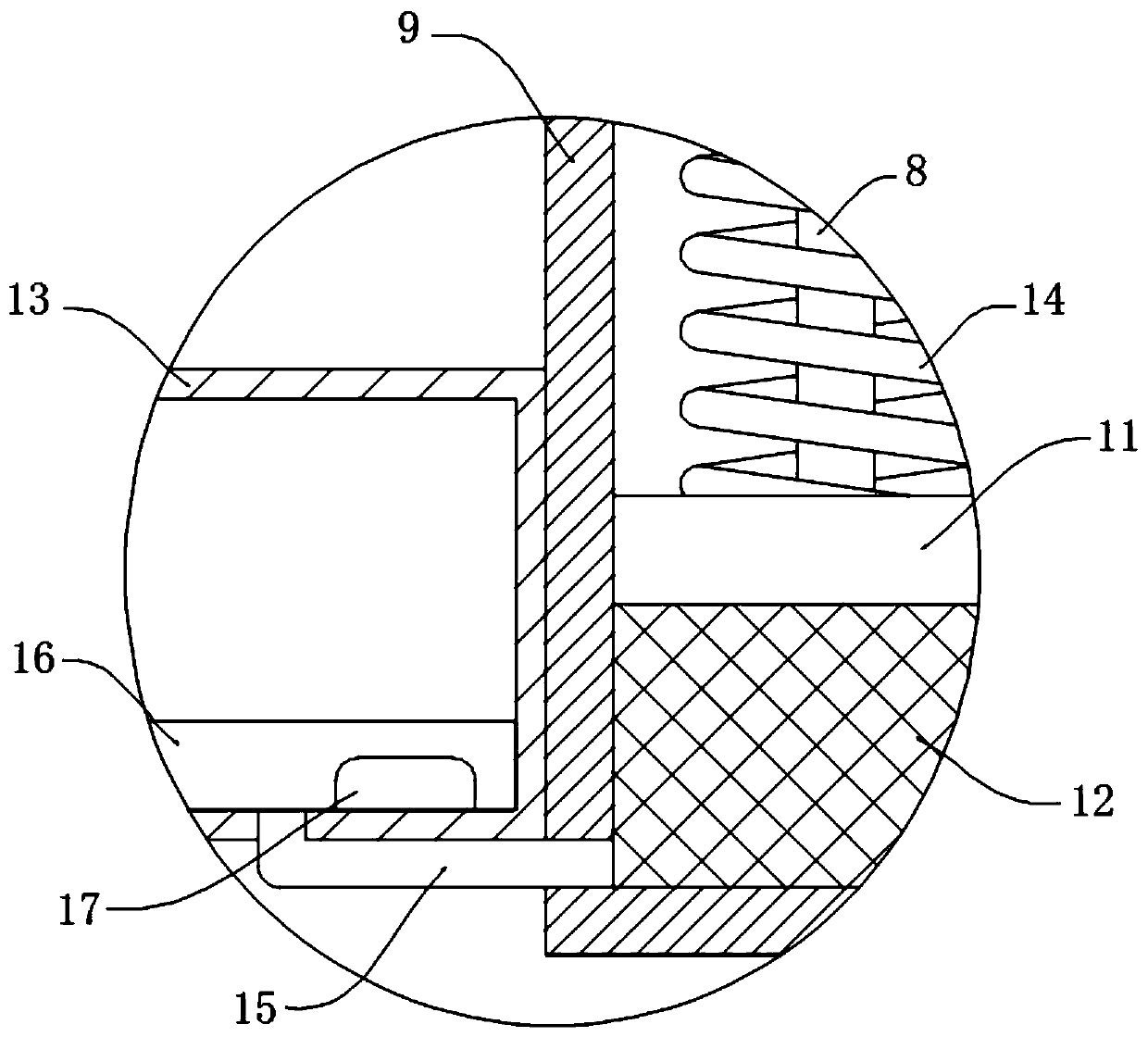
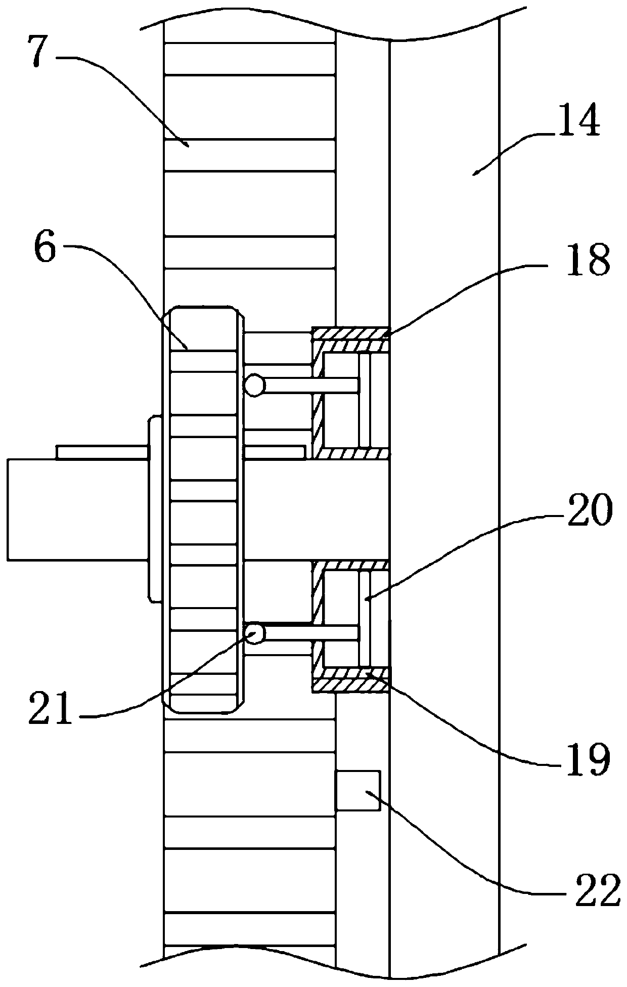
[0021] refer to Figure 1-3 , an overcurrent protector for electric power, comprising a fixed ring 1, the inner ring part of the fixed ring 1 is rotatably connected with a turntable 2, a section of conductive layer 3 and a resistance layer 4 are arranged on the fixed ring 1, and a conductive block is arranged in the turntable 2 5. The conductive layer 3 is electrically connected to the external power supply, the rotation center of the turntable 2 is fixedly connected to the gear 6, the gear 6 is meshed with the rack 7, and the bottom of the rack 7 is connected to the transmission device;

[0022] The transmission device includes a connecting rod 8, which is fixedly connected to the bottom of the rack 7 and a sleeve 9 is connected to the bottom of the connecting rod 8, the connecting rod 8 penetrates the top wall of the sleeve 9 and is sealed and slidably connected with the sleeve 9. A piston 10 is sealed and slidably connected in the barrel 9, and one end of the connecting rod...


PUM


Abstract

The invention discloses an overcurrent protector for electric power. The overcurrent protector comprises a fixation ring. The inner ring part of the fixation ring is rotationally connected with a rotary disc; a section of conductive layer and a resistance layer are arranged on the fixation ring; a conductive block is arranged in the rotary disc; the conducting layer is electrically connected withan external power supply conveying line; a gear is fixedly connected to the rotation center of the rotary disc; the gear is meshed with a toothed bar; the bottom of the toothed bar is connected with atransmission device; the transmission device comprises a connecting rod; the bottom of the connecting rod is connected with a sleeve; and a piston is connected in the sleeve in a sealed and sliding mode. The overcurrent protector has the advantages that metal solid sodium realizes two morphological changes of liquefaction and gasification at different heating temperatures under an overload current and a short-circuit current, and the two states are respectively processed under the action of the transmission device; during the short-circuit current, a circuit is disconnected, and during the overload current, a larger resistor is additionally connected; and therefore, the functions of protecting and adjusting the circuit current are achieved.

Description

technical field [0001] The invention relates to the technical field related to electric power, in particular to an overcurrent processor for electric power. Background technique [0002] In an electrical system, overcurrent or excess current is a situation in which a greater than expected current flows through conductors, causing excessive heating, and a risk of fire or damage to equipment. Possible causes of overcurrent include short circuits, excessive loads, improper design, or ground faults. Fuses, circuit breakers, temperature sensors and current limiters are often used to control the risk of overcurrent. [0003] In the use of household electrical appliances, the treatment methods for overload current and short-circuit current are different. The current of overload current is generally not many times the current carrying capacity of the circuit. shortening, after a period of time, it will cause disasters and cause damage to electrical appliances. The damage is caused...

Claims


Application Information

Patent Timeline
Patent Type & Authority Applications(China)
IPC IPC(8): H01H71/14H01H71/20H01H71/12
CPCH01H71/121H01H71/14H01H71/20
Inventor 曲相霖
Owner 曲相霖
Learn More