Passive long-distance wireless charging system

A long-distance wireless and charging system technology, applied in current collectors, electric vehicles, electrical components, etc., can solve the problems of limited wireless charging distance and charging location, and achieve the effects of convenient charging, high safety, and long receiving distance.

Active Publication Date: 2021-06-29
SHANGHAI BINY ELECTRIC
View PDF0 Cites 0 Cited by
  • Summary
  • Abstract
  • Description
  • Claims
  • Application Information

AI Technical Summary

Problems solved by technology

[0005] The invention provides a passive long-distance wireless charging system to solve the problems of limited wireless charging distance and limited charging position of existing wearable devices

Method used


Image

  • Passive long-distance wireless charging system
  • Passive long-distance wireless charging system
  • Passive long-distance wireless charging system

Examples


Embodiment 1

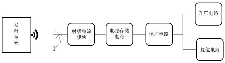
[0036] refer to figure 1The present embodiment provides a passive long-distance wireless charging system, the wireless charging system is composed of a transmitting unit for transmitting electromagnetic wave signals and a receiving unit for receiving electromagnetic wave signals; the receiving unit includes a receiving antenna, a radio frequency rectifier module, a power storage circuit and an Voltage circuit; wherein the radio frequency rectification module includes a first impedance matching circuit, a radio frequency rectification circuit, and a second impedance matching circuit; the receiving unit receives the electromagnetic wave signal emitted by the transmitting unit through the receiving antenna; the output end of the receiving antenna is connected to the The input end of the radio frequency rectification circuit, the output end of the radio frequency rectification circuit is connected to the input end of the power storage circuit through the second impedance matching c...

Embodiment 2

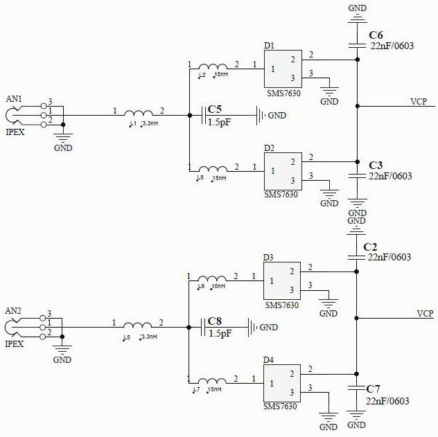
[0050] refer to figure 2 , a passive long-distance wireless charging system provided in this embodiment, on the basis of the above-mentioned embodiment 1, the difference is that it includes a first receiving antenna, a second receiving antenna, a first radio frequency rectification module and a second radio frequency A rectification module, wherein the first radio frequency rectification module includes a first radio frequency rectification circuit, a second radio frequency rectification circuit, a first impedance matching circuit and a second impedance matching circuit, wherein the input end of the first radio frequency rectification module is connected to the lead of the first receiving antenna Pin 1, the circuit structure of the first radio frequency rectification module is the same as that of the radio frequency rectification module in embodiment 1.

[0051] In this embodiment, the third radio frequency rectification circuit includes an inductor L6 and a radio frequency r...


PUM


Abstract

The present invention provides a passive long-distance wireless charging system. The wireless charging system is composed of a transmitting unit for transmitting electromagnetic wave signals and a receiving unit for receiving electromagnetic wave signals; the receiving unit includes a receiving antenna, a first impedance matching circuit, a radio frequency rectification circuit, and a second Two impedance matching circuits, power storage circuits and boosting circuits; the receiving unit receives the electromagnetic wave signal emitted by the transmitting unit through the receiving antenna, the output end of the receiving antenna is connected to the input end of the radio frequency rectification circuit through the first impedance matching circuit, and the radio frequency rectification circuit The output terminal is connected to the input terminal of the power storage circuit through the second impedance matching circuit, the output terminal of the power storage circuit is connected to the input terminal of the boost circuit, and the output terminal of the boost circuit is connected to the load to supply power for the load. The invention enables the device to be charged to realize relatively long-distance wireless charging through the receiving antenna, and solves the problems of limited wireless charging distance and limited charging position of existing wearable devices.

Description

technical field [0001] The invention relates to the technical field of wireless charging, in particular to a passive long-distance wireless charging system. Background technique [0002] Existing wearable devices are favored by more and more users because of their powerful functions. For wearable devices, the biggest challenge is how to properly and conveniently supply them with continuous power, and for many current wristband and watch designs, users must first take them off and plug them into wired chargers. Charging, charging is more troublesome. [0003] In order to solve the above problems, many products adopt an electromagnetic induction charging scheme. This solution utilizes resonant coils to conduct electrical energy. Specifically, a sending coil is set in the charger, and a receiving coil is set on the wearable device. By applying a changing current to the sending coil to generate a change in the electromagnetic field, the changing electromagnetic field is coupl...

Claims


Application Information

Patent Timeline
Patent Type & Authority Patents(China)
IPC IPC(8): H02J7/02H02J50/20H02J50/40H02H7/12
CPCH02H7/1213H02J50/20H02J50/40
Inventor 严少斌严飞飞轩北松韦小东王浩张成刘明生
Owner SHANGHAI BINY ELECTRIC
Why Eureka
Try Eureka